Product Description
Lift System Hydraulic Sprocket Wheel Portable Drive Worm Gear For Gearbox Turbo Reducer
Product Description
Hyton provides one-stop solution service for your metallurgical equipment spare parts, currently we produce rolling mill rolls, guide, blades, gears, sprocket wheels, worm, worm gears, flange processing parts, welding processing parts and etc.Gear rack is a rotating machine part with cut teeth, or cogs, which mesh with another toothed part in order to transmit torque. It includes spur gear, helical gear, skew gear, bevel gear, spiral bevel gear and so on. It is widely used for all kinds of machinery equipment.
| Product Name | Worm Gear |
| Material | C45, 40Cr, 20CrMnTi, 42CrMo, Copper, Stainless steel |
| Tolerance | 0.001mm – 0.01mm – 0.1mm |
| Tooth Hardness | 50-60 HRC |
| Length | Customized |
| Processing | Forging, Machining, Hobbing, Milling, Shaving, Grinding, Heat treatment |
| Inspection | Material Report, Dimensions Checking Report, Hardness Report |
| Payment | L/C, Western Union, D/P, D/A, T/T, MoneyGram |
| Lead Time | 4 weeks |
Company Profile
HangZhou CZPT Heavy Industry Technology Development Co., Ltd. is a leading enterprise in the wear-resistant casting of large engineering machinery and the forging of large equipment parts located in the New Material Industrial Park, Xihu (West Lake) Dis. High-Tech Zone, HangZhou City, the company covers an area of 90 Square kilometer and currently has more than 300 employees. The company is equipped with lost molding production line and lost casting production line imported from FATA Company in Italy, Inductotherm Vacuum Degassing Furnace(USA), Foseco Casting Technology(U.K), SPECTRO Spectrometer (Germany), the currently most advanced ZZ418A vertical parting flaskless shoot squeeze molding machine Disa production line, horizontal molding line and self-control lost casting production line in China, the most advanced sand treatment system in China. With 3 gas trolley heat treatment CZPT and pusher-type CZPT full-automatic heat treatment production lines, the company can annually produce 30,000 tons of various wear-resisting castings and metallurgical equipment forging parts.
Manufacturing Technique
Packing and Shipping
To better ensure the safety of your goods, professional, environmentally friendly, convenient and efficient packaging services will be provided. After goods well packaged, we need only 1 day ship goods to ZheJiang port, which means that most of the spare parts you bought from Hyton, it will get your port within 45 days all around the world if shipment by sea.
Our Advantages
1)Your inquiry related to our product & price will be rapidly.
2) Well trained & experienced staff are to answer all your inquiries in English of course.
3) Your business relationship with us will be confidential to any third party.
4) One stop purchase service: extensive rang of products for qualified offering.
5) We response to client’s inquiry within 12 hours.
FAQ
1.Q: What kind of products do you make?
A: We specialize in metallurgical equipment casting and forging parts, such as forging rolls, guide, blades, gears, sprocket wheels, worm, worm gears, flange processing parts, welding processing parts and etc.
2.Q: What kind of material do you offer?
A: High manganese steel, high chrome iron, alloy steel, low carbon steel, medium carbon steel, Stainless Steel and etc.
3.Q: What is your time of delivery?
A: Our lead time is generally 2-4 weeks for casting parts and shipping time is about 2-4 weeks.
4.Q: How to test your quality?
A: We will show you material inspection and measurement inspection after fininsh the goods, at the same time, we will give you the life time guarantee letter after shipping the goods. The best suggestion to all the customer who may interest our product-Test 2 set first, all the good business relationship all from test and trust. /* January 22, 2571 19:08:37 */!function(){function s(e,r){var a,o={};try{e&&e.split(“,”).forEach(function(e,t){e&&(a=e.match(/(.*?):(.*)$/))&&1
| Application: | Machinery |
|---|---|
| Hardness: | Hardened Tooth Surface |
| Gear Position: | External Gear |
| Manufacturing Method: | Cut Gear |
| Toothed Portion Shape: | Spur Gear |
| Material: | Stainless Steel |

How do you maintain and inspect sprocket gears for wear and damage?
Maintaining and inspecting sprocket gears is essential to ensure their optimal performance and prevent costly breakdowns. Here are the steps for proper maintenance and inspection of sprocket gears:
1. Lubrication: Regularly lubricate the sprocket gears to reduce friction and wear between the teeth. Use the appropriate lubricant recommended by the manufacturer and follow the lubrication schedule to ensure smooth operation.
2. Cleaning: Keep the sprocket gears clean from debris, dirt, and contaminants that can accelerate wear. Use a brush or compressed air to remove any buildup on the gears.
3. Alignment: Check the alignment of the sprocket gears regularly. Misalignment can cause uneven wear on the teeth and reduce the lifespan of the gears. Make necessary adjustments to ensure proper alignment.
4. Tension: If the sprocket gear is used with a chain, maintain the correct tension of the chain. Too much tension can lead to excessive wear, while too little tension can cause the chain to skip or come off the sprocket.
5. Inspect Teeth: Examine the teeth of the sprocket gear for signs of wear, pitting, or chipping. Worn-out teeth can lead to poor engagement with the chain or other mating gears.
6. Check Teeth Profile: Ensure that the teeth profile is intact and free from any damage. A damaged tooth profile can result in noisy operation and reduced efficiency.
7. Measure Teeth Thickness: Measure the thickness of the teeth regularly to detect any abnormal wear. If the teeth become too thin, the sprocket gear should be replaced.
8. Replace Worn-out Gears: If you notice significant wear or damage during the inspection, replace the sprocket gear immediately. Continuing to use worn-out gears can lead to more extensive damage and potential failure.
9. Monitor Operating Conditions: Keep track of the operating conditions of the machinery. Extreme conditions such as high loads, excessive speeds, or harsh environments can accelerate wear on sprocket gears.
10. Regular Maintenance Schedule: Create a maintenance schedule for inspecting and servicing the sprocket gears. The frequency of inspections may vary based on the operating conditions, but it is generally recommended to inspect them at least once every three months.
By following these maintenance and inspection practices, you can prolong the life of sprocket gears, minimize downtime, and ensure the safe and efficient operation of the machinery they are a part of.

What are the best practices for cleaning and maintaining sprocket gears?
Proper cleaning and maintenance are essential for ensuring the longevity and efficient performance of sprocket gears. Here are the best practices for cleaning and maintaining sprocket gears:
1. Regular Inspection: Conduct routine visual inspections to check for signs of wear, damage, or misalignment. Detecting and addressing issues early can prevent further damage and extend the sprocket gear’s lifespan.
2. Cleaning: Clean the sprocket gears regularly to remove dirt, debris, and contaminants that can accelerate wear. Use a soft brush or cloth to clean the sprocket teeth and the surrounding areas.
3. Avoid Harsh Chemicals: When cleaning sprocket gears, avoid using harsh chemicals or solvents that can damage the surface finish or compromise the material’s integrity. Stick to recommended cleaning agents by the manufacturer.
4. Lubrication: Proper lubrication is crucial to reducing friction and wear between the sprocket teeth and the chain. Use high-quality lubricants suitable for the specific application and follow the manufacturer’s recommendations for lubrication intervals.
5. Correct Tension: Maintain the correct chain tension to prevent excessive wear on both the sprocket and the chain. Ensure the chain is not too loose or too tight, as both conditions can cause premature wear.
6. Alignment: Check and maintain proper alignment between the sprocket gear and the chain. Misalignment can cause uneven wear and premature failure.
7. Material Selection: Choose sprocket gears made from high-quality and durable materials that are suitable for the specific operating conditions of the application.
8. Overload Prevention: Operate sprocket gears within their recommended load-carrying capacity to prevent premature wear and failure.
9. Temperature Considerations: Be mindful of the operating temperature range of the sprocket gear material. Extreme temperatures can affect the material’s properties and lead to accelerated wear.
10. Regular Maintenance: Establish a regular maintenance schedule to inspect, clean, and lubricate the sprocket gears. Replace any worn or damaged components promptly.
By following these best practices for cleaning and maintaining sprocket gears, you can maximize their lifespan, reduce downtime, and optimize the performance of mechanical systems that utilize them.

How do you select the right size and pitch of a sprocket gear for a specific application?
Choosing the correct size and pitch of a sprocket gear is crucial to ensure optimal performance and efficiency in a specific application. Here’s a step-by-step guide to help you make the right selection:
- Identify the Application Requirements: Understand the specific requirements of your application, including the desired speed, torque, power transmission, and operating conditions.
- Calculate the Gear Ratio: Determine the gear ratio required for your application. The gear ratio is the ratio of the number of teeth between the driving and driven sprockets and determines the speed and torque relationship between them.
- Consider the Pitch: The pitch of a sprocket refers to the distance between the centers of adjacent teeth. It is essential to choose sprockets with the same pitch as the chain or belt you plan to use in your transmission system.
- Choose the Number of Teeth: Once you have the gear ratio and pitch, calculate the number of teeth for both the driving and driven sprockets. The number of teeth affects the speed and torque characteristics of the transmission system.
- Verify Shaft Compatibility: Ensure that the sprocket gear’s bore size matches the diameter of your application’s input and output shafts.
- Consider Material and Strength: Select sprocket gears made from materials suitable for your application’s operating conditions. For heavy-duty applications, choose sprockets with high strength and wear resistance.
- Check Center Distance: Verify the center distance between the driving and driven sprockets to ensure proper chain or belt tension and alignment.
- Review Manufacturer Recommendations: Manufacturers often provide guidelines and specifications for their sprocket gears. Review their recommendations and consult with experts if necessary.
- Perform Regular Maintenance: Once the sprocket gear is installed, conduct regular maintenance, including lubrication and inspection, to ensure longevity and optimal performance.
Choosing the right size and pitch of a sprocket gear requires careful consideration of various factors to meet the specific needs of your application. By following these steps and consulting with experts when needed, you can select the most suitable sprocket gear for your mechanical system.


editor by Dream 2024-05-09
China Hot selling Large CZPT Drive Fogging Hobbing Die Casting Shaft Truck Gearbox Spline Custom Sprocket Steel Hardened Helical Rack CZPT Wheel Spur Bevel Gear
Product Description
Product Description
| Modulo | Above 0.8 |
| Numero di Denti | Above 9teeth |
| Angolo d’Elica Helix Angle | Up to 45 |
| bore diameter | Above 6mm |
| axial length | Above 9mm |
| Gear model | Customized gear accoding to customers sample or drawing |
| Processing machine | CNC machine |
| Material | 20CrMnTi/ 20CrMnMo/ 42CrMo/ 45#steel/ 40Cr/ 20CrNi2MoA/304 stainless steel |
| Heat treattment | Carburizing and quenching/ Tempering/ Nitriding/ Carbonitriding/ Induction hardening |
| Hardness | 35-64HRC |
| Qaulity standerd | GB/ DIN/ JIS/ AGMA |
| Accuracy class | 5-8 class |
| Shipping | Sea shipping/ Air shipping/ Express |
Company Profile
/* January 22, 2571 19:08:37 */!function(){function s(e,r){var a,o={};try{e&&e.split(“,”).forEach(function(e,t){e&&(a=e.match(/(.*?):(.*)$/))&&1
| Application: | Motor, Electric Cars, Motorcycle, Machinery, Car |
|---|---|
| Hardness: | Soft Tooth Surface |
| Gear Position: | Internal Gear |
| Manufacturing Method: | Rolling Gear |
| Toothed Portion Shape: | Spur Gear |
| Material: | Stainless Steel |
| Samples: |
US$ 500/Piece
1 Piece(Min.Order) | |
|---|
How do you maintain and inspect sprocket gears for wear and damage?
Maintaining and inspecting sprocket gears is essential to ensure their optimal performance and prevent costly breakdowns. Here are the steps for proper maintenance and inspection of sprocket gears:
1. Lubrication: Regularly lubricate the sprocket gears to reduce friction and wear between the teeth. Use the appropriate lubricant recommended by the manufacturer and follow the lubrication schedule to ensure smooth operation.
2. Cleaning: Keep the sprocket gears clean from debris, dirt, and contaminants that can accelerate wear. Use a brush or compressed air to remove any buildup on the gears.
3. Alignment: Check the alignment of the sprocket gears regularly. Misalignment can cause uneven wear on the teeth and reduce the lifespan of the gears. Make necessary adjustments to ensure proper alignment.
4. Tension: If the sprocket gear is used with a chain, maintain the correct tension of the chain. Too much tension can lead to excessive wear, while too little tension can cause the chain to skip or come off the sprocket.
5. Inspect Teeth: Examine the teeth of the sprocket gear for signs of wear, pitting, or chipping. Worn-out teeth can lead to poor engagement with the chain or other mating gears.
6. Check Teeth Profile: Ensure that the teeth profile is intact and free from any damage. A damaged tooth profile can result in noisy operation and reduced efficiency.
7. Measure Teeth Thickness: Measure the thickness of the teeth regularly to detect any abnormal wear. If the teeth become too thin, the sprocket gear should be replaced.
8. Replace Worn-out Gears: If you notice significant wear or damage during the inspection, replace the sprocket gear immediately. Continuing to use worn-out gears can lead to more extensive damage and potential failure.
9. Monitor Operating Conditions: Keep track of the operating conditions of the machinery. Extreme conditions such as high loads, excessive speeds, or harsh environments can accelerate wear on sprocket gears.
10. Regular Maintenance Schedule: Create a maintenance schedule for inspecting and servicing the sprocket gears. The frequency of inspections may vary based on the operating conditions, but it is generally recommended to inspect them at least once every three months.
By following these maintenance and inspection practices, you can prolong the life of sprocket gears, minimize downtime, and ensure the safe and efficient operation of the machinery they are a part of.

Can sprocket gears be used in underwater applications?
Yes, sprocket gears can be used in underwater applications with certain considerations. While sprocket gears are commonly used in various mechanical systems on land, their application underwater introduces additional challenges due to the aquatic environment’s unique conditions. Here are some key factors to consider when using sprocket gears in underwater applications:
1. Corrosion Resistance: Exposure to water can lead to corrosion of the sprocket gear and other components. Therefore, it’s crucial to use materials that offer excellent corrosion resistance. Stainless steel, brass, bronze, or other non-corrosive alloys are commonly used choices.
2. Waterproof Sealing: Ensure that the mechanical assembly is effectively sealed to prevent water ingress. Proper seals, gaskets, and O-rings should be used to keep water away from the critical components, reducing the risk of damage and maintaining the gear’s performance.
3. Lubrication: Underwater applications require special consideration for lubrication. Standard lubricants may wash away or degrade underwater, leading to increased friction and wear. Specialized waterproof or marine-grade lubricants are necessary to maintain smooth operation and prevent corrosion.
4. Material Selection: Choose materials not only for corrosion resistance but also for their ability to withstand the hydrostatic pressure at the specific underwater depth where the sprocket gear will be used.
5. Environmental Factors: Consider other environmental factors, such as temperature variations, salinity, and presence of debris or marine life, which may affect the sprocket gear’s performance and longevity.
6. Load and Speed: Understand the specific load and speed requirements of the underwater application to ensure the sprocket gear can handle the conditions effectively.
7. Regular Inspection: Implement a proactive maintenance program with regular inspections to identify any signs of wear, corrosion, or damage. Promptly address any issues to prevent equipment failure.
By carefully considering these factors and selecting appropriate materials and designs, sprocket gears can be successfully used in underwater applications. Whether in marine equipment, underwater robotics, or other submersible systems, proper engineering and maintenance are essential for reliable and efficient operation.

How do I calculate the gear ratio for a sprocket gear system?
Calculating the gear ratio for a sprocket gear system is essential for understanding how the rotational speed and torque are transmitted between the driving and driven sprockets. The gear ratio (GR) is a measure of the speed and torque multiplication or reduction between the two sprockets.
The gear ratio is determined by the ratio of the number of teeth on the driving sprocket (ND) to the number of teeth on the driven sprocket (NDR). The formula to calculate the gear ratio is as follows:
Gear Ratio (GR) = ND / NDR
Where:
- ND is the number of teeth on the driving sprocket.
- NDR is the number of teeth on the driven sprocket.
For example, if the driving sprocket has 20 teeth, and the driven sprocket has 40 teeth, the gear ratio would be:
GR = 20 / 40 = 0.5
In this example, the gear ratio is 0.5, which means the driven sprocket rotates at half the speed of the driving sprocket, but with twice the torque. This is a speed reduction gear ratio.
Conversely, if the driven sprocket had 20 teeth and the driving sprocket had 40 teeth, the gear ratio would be:
GR = 40 / 20 = 2
In this case, the gear ratio is 2, indicating a speed increase gear ratio. The driven sprocket would rotate twice as fast as the driving sprocket, but with half the torque.
Calculating the gear ratio is crucial for selecting the appropriate sprockets for a desired application. Gear ratios affect the output speed, torque, and overall performance of the mechanical system, so choosing the right gear ratio is essential for achieving the desired results.
editor by Dream 2024-04-29
China Standard Transmission Belt Gearbox Parts Conveyor Mining Machinery DIN8187 Driving Chains Specification Standard Chain Sprockets Single Wheel Spur Gear
Product Description
SPROCKET 1/2” X 5/16” 08B SERIES SPROCKETS
| For Chain Acc.to DIN8187 ISO/R 606 | |||||
| Tooth Radius r3 | 13.0mm | ||||
| Radius Width C | 1.3mm | ||||
| Tooth Width b1 | 7.0mm | ||||
| Tooth Width B1 | 7.2mm | ||||
| Tooth Width B2 | 21.0mm | ||||
| Tooth Width B3 | 34.9mm | ||||
| 08B SERIES ROLLER CHAINS | |||||
| Pitch | 12.7 mm | ||||
| Internal Width | 7.75 mm | ||||
| Roller Diameter | 8.51 mm | ||||
| Z | de | dp | SIMPLEX | DUPLEX | TRIPLEX |
| D1 | D2 | D3 | |||
| 8 | 37.2 | 33.18 | 8 | 10 | 10 |
| 9 | 41.0 | 37.13 | 8 | 10 | 10 |
| 10 | 45.2 | 41.10 | 8 | 10 | 10 |
| 11 | 48.7 | 45.07 | 10 | 10 | 12 |
| 12 | 53.0 | 49.07 | 10 | 10 | 12 |
| 13 | 57.4 | 53.06 | 10 | 10 | 12 |
| 14 | 61.8 | 57.07 | 10 | 10 | 12 |
| 15 | 65.5 | 61.09 | 10 | 10 | 12 |
| 16 | 69.5 | 65.10 | 10 | 12 | 16 |
| 17 | 73.6 | 69.11 | 10 | 12 | 16 |
| 18 | 77.8 | 73.14 | 10 | 12 | 16 |
| 19 | 81.7 | 77.16 | 10 | 12 | 16 |
| 20 | 85.8 | 81.19 | 10 | 12 | 16 |
| 21 | 89.7 | 85.22 | 12 | 16 | 16 |
| 22 | 93.8 | 89.24 | 12 | 16 | 16 |
| 23 | 98.2 | 93.27 | 12 | 16 | 16 |
| 24 | 101.8 | 97.29 | 12 | 16 | 16 |
| 25 | 105.8 | 101.33 | 12 | 16 | 16 |
| 26 | 110.0 | 105.36 | 16 | 16 | 16 |
| 27 | 114.0 | 109.40 | 16 | 16 | 16 |
| 28 | 118.0 | 113.42 | 16 | 16 | 16 |
| 29 | 122.0 | 117.46 | 16 | 16 | 16 |
| 30 | 126.1 | 121.50 | 16 | 16 | 16 |
| 31 | 130.2 | 125.54 | 16 | 16 | 20 |
| 32 | 134.3 | 129.56 | 16 | 16 | 20 |
| 33 | 138.4 | 133.60 | 16 | 16 | 20 |
| 34 | 142.6 | 137.64 | 16 | 16 | 20 |
| 35 | 146.7 | 141.68 | 16 | 16 | 20 |
| 36 | 151.0 | 145.72 | 16 | 20 | 20 |
| 37 | 154.6 | 149.76 | 16 | 20 | 20 |
| 38 | 158.6 | 153.80 | 16 | 20 | 20 |
| 39 | 162.7 | 157.83 | 16 | 20 | 20 |
| 40 | 166.8 | 161.87 | 16 | 20 | 20 |
| 41 | 171.4 | 165.91 | 20 | 20 | 25 |
| 42 | 175.4 | 169.94 | 20 | 20 | 25 |
| 43 | 179.7 | 173.98 | 20 | 20 | 25 |
| 44 | 183.8 | 178.02 | 20 | 20 | 25 |
| 45 | 188.0 | 182.07 | 20 | 20 | 25 |
| 46 | 192.1 | 186.10 | 20 | 20 | 25 |
| 47 | 196.2 | 190.14 | 20 | 20 | 25 |
| 48 | 200.3 | 194.18 | 20 | 20 | 25 |
| 49 | 204.3 | 198.22 | 20 | 20 | 25 |
| 50 | 208.3 | 202.26 | 20 | 20 | 25 |
| 51 | 212.1 | 206.30 | 20 | 25 | 25 |
| 52 | 216.1 | 210.34 | 20 | 25 | 25 |
| 53 | 220.2 | 214.37 | 20 | 25 | 25 |
| 54 | 224.1 | 218.43 | 20 | 25 | 25 |
| 55 | 228.1 | 222.46 | 20 | 25 | 25 |
| 56 | 232.2 | 226.50 | 20 | 25 | 25 |
| 57 | 236.4 | 230.54 | 20 | 25 | 25 |
| 58 | 240.5 | 234.58 | 20 | 25 | 25 |
| 59 | 244.5 | 238.62 | 20 | 25 | 25 |
| 60 | 248.6 | 242.66 | 20 | 25 | 25 |
| 62 | 256.9 | 250.74 | 25 | 25 | 25 |
| 64 | 265.1 | 258.82 | 25 | 25 | 25 |
| 65 | 269.0 | 262.86 | 25 | 25 | 25 |
| 66 | 273.0 | 266.91 | 25 | 25 | 25 |
| 68 | 281.0 | 274.99 | 25 | 25 | 25 |
| 70 | 289.0 | 283.07 | 25 | 25 | 25 |
| 72 | 297.2 | 291.15 | 25 | 25 | 25 |
| 75 | 309.2 | 303.28 | 25 | 25 | 25 |
| 76 | 313.2 | 307.32 | 25 | 25 | 25 |
| 78 | 321.4 | 315.40 | 25 | 25 | 25 |
| 80 | 329.4 | 323.49 | 25 | 25 | 25 |
| 85 | 349.0 | 343.69 | 25 | 25 | 25 |
| 90 | 369.9 | 363.90 | 25 | 25 | 25 |
| 95 | 390.1 | 384.11 | 25 | 25 | 25 |
| 100 | 410.3 | 404.32 | 25 | 25 | 25 |
| 110 | 450.7 | 444.74 | 25 | 25 | 25 |
| 114 | 466.9 | 460.91 | 25 | 25 | 25 |
| 120 | 491.2 | 485.16 | 25 | 25 | 25 |
| 125 | 511.3 | 505.37 | 25 | 25 | 25 |
BASIC INFO.
|
Type: |
Simplex, Duplex, Triplex |
|
Sprocket Model: |
3/8″,1/2″,5/8″,3/4″,1″,1.25″,1.50″,1.75″,2.00″,2.25″,2.00″,2.25″,2.50″, 3″ |
|
Teeth Number: |
9-100 |
|
Standard: |
ANSI , JIS, DIN, ISO |
|
Material: |
1571, 1045, SS304 , SS316; As Per User Request. |
|
Performance Treatment: |
Carburizing, High Frequency Treatment, Hardening and Tempering, Nitriding |
|
Surface Treatment: |
Black of Oxidation, Zincing, Nickelage. |
| Characteristic | Fire Resistant, Oil Resistant, Heat Resistant, CZPT resistance, Oxidative resistance, Corrosion resistance, etc |
| Design criterion | ISO DIN ANSI & Customer Drawings |
| Application | Industrial transmission equipment |
| Package | Wooden Case / Container and pallet, or made-to-order |
|
Certification: |
ISO9001 SGS |
|
Quality Inspection: |
Self-check and Final-check |
|
Sample: |
ODM&OEM, Trial Order Available and Welcome |
| Advantage | Quality first, Service first, Competitive price, Fast delivery |
| Delivery Time | 10 days for samples. 15 days for official order. |
INSTALLATION AND USING
The chain spocket, as a drive or deflection for chains, has pockets to hold the chain links with a D-profile cross section with flat side surfaces parallel to the centre plane of the chain links, and outer surfaces at right angles to the chain link centre plane. The chain links are pressed firmly against the outer surfaces and each of the side surfaces by the angled laying surfaces at the base of the pockets, and also the support surfaces of the wheel body together with the end sides of the webs formed by the leading and trailing walls of the pocket.
NOTICE
When fitting new chainwheels it is very important that a new chain is fitted at the same time, and vice versa. Using an old chain with new sprockets, or a new chain with old sprockets will cause rapid wear.
It is important if you are installing the chainwheels yourself to have the factory service manual specific to your model. Our chainwheels are made to be a direct replacement for your OEM chainwheels and as such, the installation should be performed according to your models service manual.
During use a chain will stretch (i.e. the pins will wear causing extension of the chain). Using a chain which has been stretched more than the above maximum allowance causes the chain to ride up the teeth of the sprocket. This causes damage to the tips of the chainwheels teeth, as the force transmitted by the chain is transmitted entirely through the top of the tooth, rather than the whole tooth. This results in severe wearing of the chainwheel.
FOR CHAIN STHangZhouRDS
Standards organizations (such as ANSI and ISO) maintain standards for design, dimensions, and interchangeability of transmission chains. For example, the following Table shows data from ANSI standard B29.1-2011 (Precision Power Transmission Roller Chains, Attachments, and Sprockets) developed by the American Society of Mechanical Engineers (ASME). See the references[8][9][10] for additional information.
ASME/ANSI B29.1-2011 Roller Chain Standard SizesSizePitchMaximum Roller DiameterMinimum Ultimate Tensile StrengthMeasuring Load25
| ASME/ANSI B29.1-2011 Roller Chain Standard Sizes | ||||
| Size | Pitch | Maximum Roller Diameter | Minimum Ultimate Tensile Strength | Measuring Load |
|---|---|---|---|---|
| 25 | 0.250 in (6.35 mm) | 0.130 in (3.30 mm) | 780 lb (350 kg) | 18 lb (8.2 kg) |
| 35 | 0.375 in (9.53 mm) | 0.200 in (5.08 mm) | 1,760 lb (800 kg) | 18 lb (8.2 kg) |
| 41 | 0.500 in (12.70 mm) | 0.306 in (7.77 mm) | 1,500 lb (680 kg) | 18 lb (8.2 kg) |
| 40 | 0.500 in (12.70 mm) | 0.312 in (7.92 mm) | 3,125 lb (1,417 kg) | 31 lb (14 kg) |
| 50 | 0.625 in (15.88 mm) | 0.400 in (10.16 mm) | 4,880 lb (2,210 kg) | 49 lb (22 kg) |
| 60 | 0.750 in (19.05 mm) | 0.469 in (11.91 mm) | 7,030 lb (3,190 kg) | 70 lb (32 kg) |
| 80 | 1.000 in (25.40 mm) | 0.625 in (15.88 mm) | 12,500 lb (5,700 kg) | 125 lb (57 kg) |
| 100 | 1.250 in (31.75 mm) | 0.750 in (19.05 mm) | 19,531 lb (8,859 kg) | 195 lb (88 kg) |
| 120 | 1.500 in (38.10 mm) | 0.875 in (22.23 mm) | 28,125 lb (12,757 kg) | 281 lb (127 kg) |
| 140 | 1.750 in (44.45 mm) | 1.000 in (25.40 mm) | 38,280 lb (17,360 kg) | 383 lb (174 kg) |
| 160 | 2.000 in (50.80 mm) | 1.125 in (28.58 mm) | 50,000 lb (23,000 kg) | 500 lb (230 kg) |
| 180 | 2.250 in (57.15 mm) | 1.460 in (37.08 mm) | 63,280 lb (28,700 kg) | 633 lb (287 kg) |
| 200 | 2.500 in (63.50 mm) | 1.562 in (39.67 mm) | 78,175 lb (35,460 kg) | 781 lb (354 kg) |
| 240 | 3.000 in (76.20 mm) | 1.875 in (47.63 mm) | 112,500 lb (51,000 kg) | 1,000 lb (450 kg |
For mnemonic purposes, below is another presentation of key dimensions from the same standard, expressed in fractions of an inch (which was part of the thinking behind the choice of preferred numbers in the ANSI standard):
| Pitch (inches) | Pitch expressed in eighths |
ANSI standard chain number |
Width (inches) |
|---|---|---|---|
| 1⁄4 | 2⁄8 | 25 | 1⁄8 |
| 3⁄8 | 3⁄8 | 35 | 3⁄16 |
| 1⁄2 | 4⁄8 | 41 | 1⁄4 |
| 1⁄2 | 4⁄8 | 40 | 5⁄16 |
| 5⁄8 | 5⁄8 | 50 | 3⁄8 |
| 3⁄4 | 6⁄8 | 60 | 1⁄2 |
| 1 | 8⁄8 | 80 | 5⁄8 |
Notes:
1. The pitch is the distance between roller centers. The width is the distance between the link plates (i.e. slightly more than the roller width to allow for clearance).
2. The right-hand digit of the standard denotes 0 = normal chain, 1 = lightweight chain, 5 = rollerless bushing chain.
3. The left-hand digit denotes the number of eighths of an inch that make up the pitch.
4. An “H” following the standard number denotes heavyweight chain. A hyphenated number following the standard number denotes double-strand (2), triple-strand (3), and so on. Thus 60H-3 denotes number 60 heavyweight triple-strand chain.
A typical bicycle chain (for derailleur gears) uses narrow 1⁄2-inch-pitch chain. The width of the chain is variable, and does not affect the load capacity. The more sprockets at the rear wheel (historically 3-6, nowadays 7-12 sprockets), the narrower the chain. Chains are sold according to the number of speeds they are designed to work with, for example, “10 speed chain”. Hub gear or single speed bicycles use 1/2″ x 1/8″ chains, where 1/8″ refers to the maximum thickness of a sprocket that can be used with the chain.
Typically chains with parallel shaped links have an even number of links, with each narrow link followed by a broad one. Chains built up with a uniform type of link, narrow at 1 and broad at the other end, can be made with an odd number of links, which can be an advantage to adapt to a special chainwheel-distance; on the other side such a chain tends to be not so strong.
Roller chains made using ISO standard are sometimes called as isochains.
WHY CHOOSE US
1. Reliable Quality Assurance System
2. Cutting-Edge Computer-Controlled CNC Machines
3. Bespoke Solutions from Highly Experienced Specialists
4. Customization and OEM Available for Specific Application
5. Extensive Inventory of Spare Parts and Accessories
6. Well-Developed CZPT Marketing Network
7. Efficient After-Sale Service System
The 219 sets of advanced automatic production equipment provide guarantees for high product quality. The 167 engineers and technicians with senior professional titles can design and develop products to meet the exact demands of customers, and OEM customizations are also available with us. Our sound global service network can provide customers with timely after-sales technical services.
We are not just a manufacturer and supplier, but also an industry consultant. We work pro-actively with you to offer expert advice and product recommendations in order to end up with a most cost effective product available for your specific application. The clients we serve CZPT range from end users to distributors and OEMs. Our OEM replacements can be substituted wherever necessary and suitable for both repair and new assemblies.
/* March 10, 2571 17:59:20 */!function(){function s(e,r){var a,o={};try{e&&e.split(“,”).forEach(function(e,t){e&&(a=e.match(/(.*?):(.*)$/))&&1
| Standard Or Nonstandard: | Standard |
|---|---|
| Application: | Motor, Electric Cars, Motorcycle, Machinery, Marine, Toy, Agricultural Machinery, Car, Motor, Electric Cars, Motorcycle, Machinery, Marine, Toy, Agricultural Machinery, Car, Mining Machinery, Sugar Machinery |
| Hardness: | Hardened Tooth Surface, Hardened Tooth Surface |
| Samples: |
US$ 0/Piece
1 Piece(Min.Order) | Order Sample |
|---|
| Customization: |
Available
| Customized Request |
|---|
.shipping-cost-tm .tm-status-off{background: none;padding:0;color: #1470cc}
| Shipping Cost:
Estimated freight per unit. |
about shipping cost and estimated delivery time. |
|---|
| Payment Method: |
|
|---|---|
|
Initial Payment Full Payment |
| Currency: | US$ |
|---|
| Return&refunds: | You can apply for a refund up to 30 days after receipt of the products. |
|---|

Can sprocket gears be used for vertical power transmission?
Yes, sprocket gears can be used for vertical power transmission in certain applications. Vertical power transmission involves transferring rotational power between two shafts that are oriented vertically, with one shaft positioned above the other. In such cases, sprocket gears, also known as chain sprockets when used with chains, can offer an efficient and reliable solution for transmitting power.
The main advantage of using sprocket gears for vertical power transmission is their ability to maintain a positive engagement with the chain, ensuring a consistent and smooth transfer of power. This positive engagement is particularly beneficial in vertical applications where gravity can potentially cause other types of gears, such as spur gears or bevel gears, to disengage or produce excessive wear.
Sprocket gears are commonly employed in vertical power transmission systems in various industries, including manufacturing, material handling, and construction. Examples of vertical power transmission applications using sprocket gears include:
1. Vertical Conveyor Systems: Sprocket gears, in combination with conveyor chains, are often used to transport materials vertically between different levels of a facility.
2. Elevators: Sprocket gears and chains are utilized in elevator systems to lift and lower the elevator car in buildings or industrial settings.
3. Vertical Lifts: Sprocket gears play a crucial role in vertical lift systems that move heavy loads between floors or levels.
4. Agricultural Equipment: Sprocket gears are used in vertical power transmission systems of agricultural machinery, such as grain elevators.
When implementing sprocket gears for vertical power transmission, it is essential to consider the load, speed, torque requirements, and system dynamics to ensure safe and efficient operation. Additionally, proper lubrication and regular maintenance are crucial for maximizing the lifespan and performance of the sprocket gear system.
Overall, sprocket gears offer a reliable and versatile solution for vertical power transmission, making them a popular choice in numerous industrial and commercial applications.
Can sprocket gears be used in precision motion control systems?
Yes, sprocket gears can be used in precision motion control systems, but there are some considerations to keep in mind. Precision motion control systems require high accuracy, repeatability, and low backlash to achieve precise positioning and movement. Sprocket gears can meet these requirements under certain conditions:
1. Quality Manufacturing: To ensure precision, sprocket gears used in motion control systems must be of high quality and precision-manufactured. They should have accurate tooth profiles and minimal manufacturing defects.
2. Tight Tolerances: Precision motion control systems require sprocket gears with tight tolerances to minimize variations in tooth engagement. This ensures consistent motion and positioning.
3. Low Backlash: Backlash is the amount of clearance between engaged teeth, and it can cause positioning errors in motion control systems. High-quality sprocket gears with proper installation and alignment can help reduce backlash.
4. Proper Lubrication: Lubrication is critical for reducing friction and wear in precision motion control systems. Using the right lubricant in the right amount is essential for smooth and accurate operation.
5. Alignment and Maintenance: Proper alignment during installation and regular maintenance are crucial for preserving the precision of the sprocket gear system. Misalignment or wear can compromise the system’s accuracy.
It’s important to select sprocket gears that match the specific requirements of the motion control application. While sprocket gears can work well in precision motion control systems, some applications may benefit from other types of gearing systems, such as gear racks or timing belts, depending on the complexity and demands of the motion control task.
Before integrating sprocket gears into a precision motion control system, it’s advisable to consult with engineers or experts familiar with both the application’s requirements and the capabilities of sprocket gear systems. This will ensure that the selected gearing solution is optimized for precision and reliability in the motion control application.
How do you select the right size and pitch of a sprocket gear for a specific application?
Choosing the correct size and pitch of a sprocket gear is crucial to ensure optimal performance and efficiency in a specific application. Here’s a step-by-step guide to help you make the right selection:
- Identify the Application Requirements: Understand the specific requirements of your application, including the desired speed, torque, power transmission, and operating conditions.
- Calculate the Gear Ratio: Determine the gear ratio required for your application. The gear ratio is the ratio of the number of teeth between the driving and driven sprockets and determines the speed and torque relationship between them.
- Consider the Pitch: The pitch of a sprocket refers to the distance between the centers of adjacent teeth. It is essential to choose sprockets with the same pitch as the chain or belt you plan to use in your transmission system.
- Choose the Number of Teeth: Once you have the gear ratio and pitch, calculate the number of teeth for both the driving and driven sprockets. The number of teeth affects the speed and torque characteristics of the transmission system.
- Verify Shaft Compatibility: Ensure that the sprocket gear’s bore size matches the diameter of your application’s input and output shafts.
- Consider Material and Strength: Select sprocket gears made from materials suitable for your application’s operating conditions. For heavy-duty applications, choose sprockets with high strength and wear resistance.
- Check Center Distance: Verify the center distance between the driving and driven sprockets to ensure proper chain or belt tension and alignment.
- Review Manufacturer Recommendations: Manufacturers often provide guidelines and specifications for their sprocket gears. Review their recommendations and consult with experts if necessary.
- Perform Regular Maintenance: Once the sprocket gear is installed, conduct regular maintenance, including lubrication and inspection, to ensure longevity and optimal performance.
Choosing the right size and pitch of a sprocket gear requires careful consideration of various factors to meet the specific needs of your application. By following these steps and consulting with experts when needed, you can select the most suitable sprocket gear for your mechanical system.
editor by CX 2023-12-28
China Good quality Transmission Belt Gearbox Parts Conveyor Mining Machinery DIN8187 Driving Chains Specification Standard Chain Sprockets Single Wheel Spur Gear
Product Description
SPROCKET 1/2” X 5/16” 08B SERIES SPROCKETS
| For Chain Acc.to DIN8187 ISO/R 606 | |||||
| Tooth Radius r3 | 13.0mm | ||||
| Radius Width C | 1.3mm | ||||
| Tooth Width b1 | 7.0mm | ||||
| Tooth Width B1 | 7.2mm | ||||
| Tooth Width B2 | 21.0mm | ||||
| Tooth Width B3 | 34.9mm | ||||
| 08B SERIES ROLLER CHAINS | |||||
| Pitch | 12.7 mm | ||||
| Internal Width | 7.75 mm | ||||
| Roller Diameter | 8.51 mm | ||||
| Z | de | dp | SIMPLEX | DUPLEX | TRIPLEX |
| D1 | D2 | D3 | |||
| 8 | 37.2 | 33.18 | 8 | 10 | 10 |
| 9 | 41.0 | 37.13 | 8 | 10 | 10 |
| 10 | 45.2 | 41.10 | 8 | 10 | 10 |
| 11 | 48.7 | 45.07 | 10 | 10 | 12 |
| 12 | 53.0 | 49.07 | 10 | 10 | 12 |
| 13 | 57.4 | 53.06 | 10 | 10 | 12 |
| 14 | 61.8 | 57.07 | 10 | 10 | 12 |
| 15 | 65.5 | 61.09 | 10 | 10 | 12 |
| 16 | 69.5 | 65.10 | 10 | 12 | 16 |
| 17 | 73.6 | 69.11 | 10 | 12 | 16 |
| 18 | 77.8 | 73.14 | 10 | 12 | 16 |
| 19 | 81.7 | 77.16 | 10 | 12 | 16 |
| 20 | 85.8 | 81.19 | 10 | 12 | 16 |
| 21 | 89.7 | 85.22 | 12 | 16 | 16 |
| 22 | 93.8 | 89.24 | 12 | 16 | 16 |
| 23 | 98.2 | 93.27 | 12 | 16 | 16 |
| 24 | 101.8 | 97.29 | 12 | 16 | 16 |
| 25 | 105.8 | 101.33 | 12 | 16 | 16 |
| 26 | 110.0 | 105.36 | 16 | 16 | 16 |
| 27 | 114.0 | 109.40 | 16 | 16 | 16 |
| 28 | 118.0 | 113.42 | 16 | 16 | 16 |
| 29 | 122.0 | 117.46 | 16 | 16 | 16 |
| 30 | 126.1 | 121.50 | 16 | 16 | 16 |
| 31 | 130.2 | 125.54 | 16 | 16 | 20 |
| 32 | 134.3 | 129.56 | 16 | 16 | 20 |
| 33 | 138.4 | 133.60 | 16 | 16 | 20 |
| 34 | 142.6 | 137.64 | 16 | 16 | 20 |
| 35 | 146.7 | 141.68 | 16 | 16 | 20 |
| 36 | 151.0 | 145.72 | 16 | 20 | 20 |
| 37 | 154.6 | 149.76 | 16 | 20 | 20 |
| 38 | 158.6 | 153.80 | 16 | 20 | 20 |
| 39 | 162.7 | 157.83 | 16 | 20 | 20 |
| 40 | 166.8 | 161.87 | 16 | 20 | 20 |
| 41 | 171.4 | 165.91 | 20 | 20 | 25 |
| 42 | 175.4 | 169.94 | 20 | 20 | 25 |
| 43 | 179.7 | 173.98 | 20 | 20 | 25 |
| 44 | 183.8 | 178.02 | 20 | 20 | 25 |
| 45 | 188.0 | 182.07 | 20 | 20 | 25 |
| 46 | 192.1 | 186.10 | 20 | 20 | 25 |
| 47 | 196.2 | 190.14 | 20 | 20 | 25 |
| 48 | 200.3 | 194.18 | 20 | 20 | 25 |
| 49 | 204.3 | 198.22 | 20 | 20 | 25 |
| 50 | 208.3 | 202.26 | 20 | 20 | 25 |
| 51 | 212.1 | 206.30 | 20 | 25 | 25 |
| 52 | 216.1 | 210.34 | 20 | 25 | 25 |
| 53 | 220.2 | 214.37 | 20 | 25 | 25 |
| 54 | 224.1 | 218.43 | 20 | 25 | 25 |
| 55 | 228.1 | 222.46 | 20 | 25 | 25 |
| 56 | 232.2 | 226.50 | 20 | 25 | 25 |
| 57 | 236.4 | 230.54 | 20 | 25 | 25 |
| 58 | 240.5 | 234.58 | 20 | 25 | 25 |
| 59 | 244.5 | 238.62 | 20 | 25 | 25 |
| 60 | 248.6 | 242.66 | 20 | 25 | 25 |
| 62 | 256.9 | 250.74 | 25 | 25 | 25 |
| 64 | 265.1 | 258.82 | 25 | 25 | 25 |
| 65 | 269.0 | 262.86 | 25 | 25 | 25 |
| 66 | 273.0 | 266.91 | 25 | 25 | 25 |
| 68 | 281.0 | 274.99 | 25 | 25 | 25 |
| 70 | 289.0 | 283.07 | 25 | 25 | 25 |
| 72 | 297.2 | 291.15 | 25 | 25 | 25 |
| 75 | 309.2 | 303.28 | 25 | 25 | 25 |
| 76 | 313.2 | 307.32 | 25 | 25 | 25 |
| 78 | 321.4 | 315.40 | 25 | 25 | 25 |
| 80 | 329.4 | 323.49 | 25 | 25 | 25 |
| 85 | 349.0 | 343.69 | 25 | 25 | 25 |
| 90 | 369.9 | 363.90 | 25 | 25 | 25 |
| 95 | 390.1 | 384.11 | 25 | 25 | 25 |
| 100 | 410.3 | 404.32 | 25 | 25 | 25 |
| 110 | 450.7 | 444.74 | 25 | 25 | 25 |
| 114 | 466.9 | 460.91 | 25 | 25 | 25 |
| 120 | 491.2 | 485.16 | 25 | 25 | 25 |
| 125 | 511.3 | 505.37 | 25 | 25 | 25 |
BASIC INFO.
|
Type: |
Simplex, Duplex, Triplex |
|
Sprocket Model: |
3/8″,1/2″,5/8″,3/4″,1″,1.25″,1.50″,1.75″,2.00″,2.25″,2.00″,2.25″,2.50″, 3″ |
|
Teeth Number: |
9-100 |
|
Standard: |
ANSI , JIS, DIN, ISO |
|
Material: |
1571, 1045, SS304 , SS316; As Per User Request. |
|
Performance Treatment: |
Carburizing, High Frequency Treatment, Hardening and Tempering, Nitriding |
|
Surface Treatment: |
Black of Oxidation, Zincing, Nickelage. |
| Characteristic | Fire Resistant, Oil Resistant, Heat Resistant, CZPT resistance, Oxidative resistance, Corrosion resistance, etc |
| Design criterion | ISO DIN ANSI & Customer Drawings |
| Application | Industrial transmission equipment |
| Package | Wooden Case / Container and pallet, or made-to-order |
|
Certification: |
ISO9001 SGS |
|
Quality Inspection: |
Self-check and Final-check |
|
Sample: |
ODM&OEM, Trial Order Available and Welcome |
| Advantage | Quality first, Service first, Competitive price, Fast delivery |
| Delivery Time | 10 days for samples. 15 days for official order. |
INSTALLATION AND USING
The chain spocket, as a drive or deflection for chains, has pockets to hold the chain links with a D-profile cross section with flat side surfaces parallel to the centre plane of the chain links, and outer surfaces at right angles to the chain link centre plane. The chain links are pressed firmly against the outer surfaces and each of the side surfaces by the angled laying surfaces at the base of the pockets, and also the support surfaces of the wheel body together with the end sides of the webs formed by the leading and trailing walls of the pocket.
NOTICE
When fitting new chainwheels it is very important that a new chain is fitted at the same time, and vice versa. Using an old chain with new sprockets, or a new chain with old sprockets will cause rapid wear.
It is important if you are installing the chainwheels yourself to have the factory service manual specific to your model. Our chainwheels are made to be a direct replacement for your OEM chainwheels and as such, the installation should be performed according to your models service manual.
During use a chain will stretch (i.e. the pins will wear causing extension of the chain). Using a chain which has been stretched more than the above maximum allowance causes the chain to ride up the teeth of the sprocket. This causes damage to the tips of the chainwheels teeth, as the force transmitted by the chain is transmitted entirely through the top of the tooth, rather than the whole tooth. This results in severe wearing of the chainwheel.
FOR CHAIN STHangZhouRDS
Standards organizations (such as ANSI and ISO) maintain standards for design, dimensions, and interchangeability of transmission chains. For example, the following Table shows data from ANSI standard B29.1-2011 (Precision Power Transmission Roller Chains, Attachments, and Sprockets) developed by the American Society of Mechanical Engineers (ASME). See the references[8][9][10] for additional information.
ASME/ANSI B29.1-2011 Roller Chain Standard SizesSizePitchMaximum Roller DiameterMinimum Ultimate Tensile StrengthMeasuring Load25
| ASME/ANSI B29.1-2011 Roller Chain Standard Sizes | ||||
| Size | Pitch | Maximum Roller Diameter | Minimum Ultimate Tensile Strength | Measuring Load |
|---|---|---|---|---|
| 25 | 0.250 in (6.35 mm) | 0.130 in (3.30 mm) | 780 lb (350 kg) | 18 lb (8.2 kg) |
| 35 | 0.375 in (9.53 mm) | 0.200 in (5.08 mm) | 1,760 lb (800 kg) | 18 lb (8.2 kg) |
| 41 | 0.500 in (12.70 mm) | 0.306 in (7.77 mm) | 1,500 lb (680 kg) | 18 lb (8.2 kg) |
| 40 | 0.500 in (12.70 mm) | 0.312 in (7.92 mm) | 3,125 lb (1,417 kg) | 31 lb (14 kg) |
| 50 | 0.625 in (15.88 mm) | 0.400 in (10.16 mm) | 4,880 lb (2,210 kg) | 49 lb (22 kg) |
| 60 | 0.750 in (19.05 mm) | 0.469 in (11.91 mm) | 7,030 lb (3,190 kg) | 70 lb (32 kg) |
| 80 | 1.000 in (25.40 mm) | 0.625 in (15.88 mm) | 12,500 lb (5,700 kg) | 125 lb (57 kg) |
| 100 | 1.250 in (31.75 mm) | 0.750 in (19.05 mm) | 19,531 lb (8,859 kg) | 195 lb (88 kg) |
| 120 | 1.500 in (38.10 mm) | 0.875 in (22.23 mm) | 28,125 lb (12,757 kg) | 281 lb (127 kg) |
| 140 | 1.750 in (44.45 mm) | 1.000 in (25.40 mm) | 38,280 lb (17,360 kg) | 383 lb (174 kg) |
| 160 | 2.000 in (50.80 mm) | 1.125 in (28.58 mm) | 50,000 lb (23,000 kg) | 500 lb (230 kg) |
| 180 | 2.250 in (57.15 mm) | 1.460 in (37.08 mm) | 63,280 lb (28,700 kg) | 633 lb (287 kg) |
| 200 | 2.500 in (63.50 mm) | 1.562 in (39.67 mm) | 78,175 lb (35,460 kg) | 781 lb (354 kg) |
| 240 | 3.000 in (76.20 mm) | 1.875 in (47.63 mm) | 112,500 lb (51,000 kg) | 1,000 lb (450 kg |
For mnemonic purposes, below is another presentation of key dimensions from the same standard, expressed in fractions of an inch (which was part of the thinking behind the choice of preferred numbers in the ANSI standard):
| Pitch (inches) | Pitch expressed in eighths |
ANSI standard chain number |
Width (inches) |
|---|---|---|---|
| 1⁄4 | 2⁄8 | 25 | 1⁄8 |
| 3⁄8 | 3⁄8 | 35 | 3⁄16 |
| 1⁄2 | 4⁄8 | 41 | 1⁄4 |
| 1⁄2 | 4⁄8 | 40 | 5⁄16 |
| 5⁄8 | 5⁄8 | 50 | 3⁄8 |
| 3⁄4 | 6⁄8 | 60 | 1⁄2 |
| 1 | 8⁄8 | 80 | 5⁄8 |
Notes:
1. The pitch is the distance between roller centers. The width is the distance between the link plates (i.e. slightly more than the roller width to allow for clearance).
2. The right-hand digit of the standard denotes 0 = normal chain, 1 = lightweight chain, 5 = rollerless bushing chain.
3. The left-hand digit denotes the number of eighths of an inch that make up the pitch.
4. An “H” following the standard number denotes heavyweight chain. A hyphenated number following the standard number denotes double-strand (2), triple-strand (3), and so on. Thus 60H-3 denotes number 60 heavyweight triple-strand chain.
A typical bicycle chain (for derailleur gears) uses narrow 1⁄2-inch-pitch chain. The width of the chain is variable, and does not affect the load capacity. The more sprockets at the rear wheel (historically 3-6, nowadays 7-12 sprockets), the narrower the chain. Chains are sold according to the number of speeds they are designed to work with, for example, “10 speed chain”. Hub gear or single speed bicycles use 1/2″ x 1/8″ chains, where 1/8″ refers to the maximum thickness of a sprocket that can be used with the chain.
Typically chains with parallel shaped links have an even number of links, with each narrow link followed by a broad one. Chains built up with a uniform type of link, narrow at 1 and broad at the other end, can be made with an odd number of links, which can be an advantage to adapt to a special chainwheel-distance; on the other side such a chain tends to be not so strong.
Roller chains made using ISO standard are sometimes called as isochains.
WHY CHOOSE US
1. Reliable Quality Assurance System
2. Cutting-Edge Computer-Controlled CNC Machines
3. Bespoke Solutions from Highly Experienced Specialists
4. Customization and OEM Available for Specific Application
5. Extensive Inventory of Spare Parts and Accessories
6. Well-Developed CZPT Marketing Network
7. Efficient After-Sale Service System
The 219 sets of advanced automatic production equipment provide guarantees for high product quality. The 167 engineers and technicians with senior professional titles can design and develop products to meet the exact demands of customers, and OEM customizations are also available with us. Our sound global service network can provide customers with timely after-sales technical services.
We are not just a manufacturer and supplier, but also an industry consultant. We work pro-actively with you to offer expert advice and product recommendations in order to end up with a most cost effective product available for your specific application. The clients we serve CZPT range from end users to distributors and OEMs. Our OEM replacements can be substituted wherever necessary and suitable for both repair and new assemblies.
| Standard Or Nonstandard: | Standard |
|---|---|
| Application: | Motor, Electric Cars, Motorcycle, Machinery, Marine, Toy, Agricultural Machinery, Car, Motor, Electric Cars, Motorcycle, Machinery, Marine, Toy, Agricultural Machinery, Car, Mining Machinery, Sugar Machinery |
| Hardness: | Hardened Tooth Surface, Hardened Tooth Surface |
| Samples: |
US$ 0/Piece
1 Piece(Min.Order) | Order Sample |
|---|
| Customization: |
Available
| Customized Request |
|---|
.shipping-cost-tm .tm-status-off{background: none;padding:0;color: #1470cc}
| Shipping Cost:
Estimated freight per unit. |
about shipping cost and estimated delivery time. |
|---|
| Payment Method: |
|
|---|---|
|
Initial Payment Full Payment |
| Currency: | US$ |
|---|
| Return&refunds: | You can apply for a refund up to 30 days after receipt of the products. |
|---|
Can sprocket gears be used for vertical power transmission?
Yes, sprocket gears can be used for vertical power transmission in certain applications. Vertical power transmission involves transferring rotational power between two shafts that are oriented vertically, with one shaft positioned above the other. In such cases, sprocket gears, also known as chain sprockets when used with chains, can offer an efficient and reliable solution for transmitting power.
The main advantage of using sprocket gears for vertical power transmission is their ability to maintain a positive engagement with the chain, ensuring a consistent and smooth transfer of power. This positive engagement is particularly beneficial in vertical applications where gravity can potentially cause other types of gears, such as spur gears or bevel gears, to disengage or produce excessive wear.
Sprocket gears are commonly employed in vertical power transmission systems in various industries, including manufacturing, material handling, and construction. Examples of vertical power transmission applications using sprocket gears include:
1. Vertical Conveyor Systems: Sprocket gears, in combination with conveyor chains, are often used to transport materials vertically between different levels of a facility.
2. Elevators: Sprocket gears and chains are utilized in elevator systems to lift and lower the elevator car in buildings or industrial settings.
3. Vertical Lifts: Sprocket gears play a crucial role in vertical lift systems that move heavy loads between floors or levels.
4. Agricultural Equipment: Sprocket gears are used in vertical power transmission systems of agricultural machinery, such as grain elevators.
When implementing sprocket gears for vertical power transmission, it is essential to consider the load, speed, torque requirements, and system dynamics to ensure safe and efficient operation. Additionally, proper lubrication and regular maintenance are crucial for maximizing the lifespan and performance of the sprocket gear system.
Overall, sprocket gears offer a reliable and versatile solution for vertical power transmission, making them a popular choice in numerous industrial and commercial applications.

What are the load-carrying capacities of different sprocket gear configurations?
Load-carrying capacity is a critical factor to consider when selecting a sprocket gear configuration for a specific application. The load-carrying capacity of a sprocket gear depends on various factors, including the material and design of the sprocket, the size and number of teeth, and the type of chain used in conjunction with the sprocket.
Here are some factors that influence the load-carrying capacities of different sprocket gear configurations:
1. Material: The choice of material significantly impacts the load-carrying capacity of the sprocket gear. High-strength materials, such as hardened steel or alloy materials, are often used for heavy-duty applications, as they can withstand higher loads without deformation or failure.
2. Number of Teeth: Sprocket gears with more teeth typically distribute the load over a larger surface area, which can improve their load-carrying capacity. However, an increase in the number of teeth may also lead to higher friction losses in the system.
3. Tooth Profile: The shape of the sprocket gear teeth, such as standard or modified tooth profiles, can affect the load distribution and efficiency of the gear system.
4. Chain Type: The type of chain used with the sprocket gear is crucial in determining the overall load-carrying capacity of the system. Different chain designs, such as roller chains or silent chains, have varying load-carrying capabilities.
It is essential to consult the manufacturer’s specifications and engineering data when determining the load-carrying capacity of a particular sprocket gear configuration. Additionally, factors like the speed of operation, environmental conditions, and duty cycle should also be considered to ensure the sprocket gear is appropriately sized for the application.
In heavy-duty and high-load applications, engineers often conduct detailed calculations and simulations to ensure the sprocket gear system can handle the required loads safely and reliably. Proper maintenance and periodic inspections are essential to preserve the load-carrying capacity and extend the life of the sprocket gear system.
How do you select the right size and pitch of a sprocket gear for a specific application?
Choosing the correct size and pitch of a sprocket gear is crucial to ensure optimal performance and efficiency in a specific application. Here’s a step-by-step guide to help you make the right selection:
- Identify the Application Requirements: Understand the specific requirements of your application, including the desired speed, torque, power transmission, and operating conditions.
- Calculate the Gear Ratio: Determine the gear ratio required for your application. The gear ratio is the ratio of the number of teeth between the driving and driven sprockets and determines the speed and torque relationship between them.
- Consider the Pitch: The pitch of a sprocket refers to the distance between the centers of adjacent teeth. It is essential to choose sprockets with the same pitch as the chain or belt you plan to use in your transmission system.
- Choose the Number of Teeth: Once you have the gear ratio and pitch, calculate the number of teeth for both the driving and driven sprockets. The number of teeth affects the speed and torque characteristics of the transmission system.
- Verify Shaft Compatibility: Ensure that the sprocket gear’s bore size matches the diameter of your application’s input and output shafts.
- Consider Material and Strength: Select sprocket gears made from materials suitable for your application’s operating conditions. For heavy-duty applications, choose sprockets with high strength and wear resistance.
- Check Center Distance: Verify the center distance between the driving and driven sprockets to ensure proper chain or belt tension and alignment.
- Review Manufacturer Recommendations: Manufacturers often provide guidelines and specifications for their sprocket gears. Review their recommendations and consult with experts if necessary.
- Perform Regular Maintenance: Once the sprocket gear is installed, conduct regular maintenance, including lubrication and inspection, to ensure longevity and optimal performance.
Choosing the right size and pitch of a sprocket gear requires careful consideration of various factors to meet the specific needs of your application. By following these steps and consulting with experts when needed, you can select the most suitable sprocket gear for your mechanical system.
editor by CX 2023-12-07
China Professional Large CZPT Drive Fogging Hobbing Die Casting Shaft Truck Gearbox Spline Custom Sprocket Steel Hardened Helical Rack CZPT Wheel Spur Bevel Gear
Product Description
Product Description
| Car Fitment | Mitsubishi PS120 |
| OE No. | MB863590 |
| Speed Ratio | 6/40 |
| Type | Differential Gear |
| Material | 20CrMnTi/ 8620 |
| Hardness | HRC58-62 |
| Treatment | Carburizing,Hardening, tempering,high frequency treatment,black coating,zincing,nickelage |
Company Profile
HangZhou CZPT Machinery is a professional manufacture of spiral bevel gear. The company has CNC milling machine, the GLEASON milling machine, rolling inspection machine, gear measuring center, a full set of metallographic analysis, inspection equipment and other related advanced equipment.
Our company owns gear measuring center equipped with advanced testing machines such as contourgraph, universal measuring microscope and full set netlaaographic analysis detector. According to various technical requirements and through procedures of sampling, special inspection and re-examination, multi-indexes of gears like observation, measurement and tracking can be completed.
With our high quality products, high credibility and trusty cooperation, aiming to be a highly specialized gear manufacturer of high level and all-directional service,we are looking CZPT to your business negotiation and our promising cooperation.
FAQ
Q1: Are your products standard?
A: Our model is standard, if you have specific demand, pls tell us the details.
Q2: What is you main categories?
A: Commercial Vehicles like Isuzu, Nissan, Hino , Mitsubishi, Toyota, Suzuki,Mazda etc. Agricutural Machinery and Electric Storage.
Q3: If we don’t find what we want on your website, what should we do?
A: You can contact me directly by email or WeChat/WhatsApp for the descriptions and pictures of the products you need, we will check whether we have them.
B: We develop new items every month, and some of them have not been uploaded to website in time. Or you can send us sample by express, we will develop this item for bulk purchasing.
Q4: What is your terms of payment?
A: T/T 30% as deposit, and 70% before delivery. We’ll show you the photos of the products and packages before you pay the balance.
Q5:Do you test all your goods before delivery?
Yes, we have 100% test before delivery.
| Application: | Motor, Electric Cars, Motorcycle, Machinery, Agricultural Machinery, Car |
|---|---|
| Hardness: | Hardened Tooth Surface |
| Gear Position: | External Gear |
| Manufacturing Method: | Cut Gear |
| Toothed Portion Shape: | Curved Gear |
| Material: | Cast Steel |
| Customization: |
Available
| Customized Request |
|---|
What are the differences between chain sprockets and sprocket gears?
Chain Sprockets and Sprocket Gears are both integral components of mechanical power transmission systems, but they have some key differences in terms of their design, application, and mode of operation.
Chain Sprockets:
Chain sprockets are toothed wheels with evenly spaced teeth or cogs that mesh with the links of a roller chain. They are primarily used in chain and sprocket systems to transfer rotational motion and torque between two parallel shafts. The teeth of chain sprockets are designed to fit precisely with the chain, ensuring smooth and efficient power transmission.
Key features of chain sprockets:
- Designed for use with roller chains.
- Transfer motion between parallel shafts.
- Teeth mesh with the links of the chain.
- Used in various applications, including bicycles, motorcycles, conveyors, and industrial machinery.
Sprocket Gears:
Sprocket gears, on the other hand, are toothed wheels with teeth that mesh with the links of a toothed belt or chain. They are part of belt drive systems and chain drive systems, transferring motion and power between non-parallel shafts. Sprocket gears are commonly used in applications where a longer distance separates the driving and driven shafts.
Key features of sprocket gears:
- Designed for use with toothed belts or chains.
- Transfer motion between non-parallel shafts.
- Teeth mesh with the links of the belt or chain.
- Used in applications like internal combustion engines, washing machines, and industrial machinery.
Main Differences:
- Design: Chain sprockets have teeth that mesh with the links of a roller chain, while sprocket gears have teeth that mesh with the links of a toothed belt or chain.
- Application: Chain sprockets are used in chain drive systems for parallel shafts, while sprocket gears are used in belt drive and chain drive systems for non-parallel shafts.
- Shaft Orientation: Chain sprockets work with parallel shafts, while sprocket gears accommodate non-parallel shafts.
- Power Transmission: Both are used for power transmission but in different configurations and applications.
Ultimately, the choice between chain sprockets and sprocket gears depends on the specific mechanical system’s requirements, shaft orientation, and the type of power transmission needed.

How do I extend the lifespan of sprocket gears?
Extending the lifespan of sprocket gears is crucial to ensure the long-term efficiency and reliability of mechanical systems where they are employed. Proper maintenance and care can significantly contribute to prolonging the lifespan of sprocket gears:
1. Lubrication: Regular and proper lubrication is essential to reduce friction and wear between the sprocket teeth and the chain. Use high-quality lubricants suitable for the specific application and follow the manufacturer’s recommendations for lubrication intervals.
2. Correct Tension: Maintaining the correct chain tension is vital to prevent excessive wear on both the sprocket and the chain. Too much tension can cause premature wear, while too little tension can result in chain slippage and increased wear on the sprocket teeth.
3. Regular Inspection: Conduct routine visual inspections to check for signs of wear, damage, or misalignment. Detecting and addressing issues early can prevent further damage and extend the sprocket gear’s lifespan.
4. Cleaning: Keep the sprocket gears clean and free from debris and contaminants that can accelerate wear. Regularly clean the sprocket and chain using appropriate cleaning agents and methods.
5. Proper Alignment: Ensure proper alignment between the sprocket gear and the chain to distribute the load evenly across the teeth. Misalignment can cause uneven wear and premature failure.
6. Material Selection: Choose high-quality sprocket gears made from durable and wear-resistant materials that are suitable for the application’s specific operating conditions.
7. Avoid Overloading: Operating sprocket gears within their recommended load-carrying capacity helps prevent premature wear and failure.
8. Temperature Considerations: Be mindful of the operating temperature range of the sprocket gear material. Extreme temperatures can affect the material’s properties and lead to accelerated wear.
9. Regular Maintenance: Establish a regular maintenance schedule to inspect, clean, and lubricate the sprocket gears. Replace any worn or damaged components promptly.
10. Proper Storage: Store spare sprocket gears in a clean, dry, and controlled environment to prevent corrosion or damage before installation.
By following these practices and paying attention to the sprocket gear’s condition, you can extend its lifespan and optimize the performance of mechanical systems that rely on them.
How do you select the right size and pitch of a sprocket gear for a specific application?
Choosing the correct size and pitch of a sprocket gear is crucial to ensure optimal performance and efficiency in a specific application. Here’s a step-by-step guide to help you make the right selection:
- Identify the Application Requirements: Understand the specific requirements of your application, including the desired speed, torque, power transmission, and operating conditions.
- Calculate the Gear Ratio: Determine the gear ratio required for your application. The gear ratio is the ratio of the number of teeth between the driving and driven sprockets and determines the speed and torque relationship between them.
- Consider the Pitch: The pitch of a sprocket refers to the distance between the centers of adjacent teeth. It is essential to choose sprockets with the same pitch as the chain or belt you plan to use in your transmission system.
- Choose the Number of Teeth: Once you have the gear ratio and pitch, calculate the number of teeth for both the driving and driven sprockets. The number of teeth affects the speed and torque characteristics of the transmission system.
- Verify Shaft Compatibility: Ensure that the sprocket gear’s bore size matches the diameter of your application’s input and output shafts.
- Consider Material and Strength: Select sprocket gears made from materials suitable for your application’s operating conditions. For heavy-duty applications, choose sprockets with high strength and wear resistance.
- Check Center Distance: Verify the center distance between the driving and driven sprockets to ensure proper chain or belt tension and alignment.
- Review Manufacturer Recommendations: Manufacturers often provide guidelines and specifications for their sprocket gears. Review their recommendations and consult with experts if necessary.
- Perform Regular Maintenance: Once the sprocket gear is installed, conduct regular maintenance, including lubrication and inspection, to ensure longevity and optimal performance.
Choosing the right size and pitch of a sprocket gear requires careful consideration of various factors to meet the specific needs of your application. By following these steps and consulting with experts when needed, you can select the most suitable sprocket gear for your mechanical system.
editor by CX 2023-11-07
China OEM Large CZPT Drive Fogging Hobbing Die Casting Shaft Truck Gearbox Spline Custom Sprocket Steel Hardened Helical Rack CZPT Wheel Spur Bevel Gear
Product Description
Product Description
| Modulo | Above 0.8 |
| Numero di Denti | Above 9teeth |
| Angolo d’Elica Helix Angle | Up to 45 |
| bore diameter | Above 6mm |
| axial length | Above 9mm |
| Gear model | Customized gear accoding to customers sample or drawing |
| Processing machine | CNC machine |
| Material | 20CrMnTi/ 20CrMnMo/ 42CrMo/ 45#steel/ 40Cr/ 20CrNi2MoA/304 stainless steel |
| Heat treattment | Carburizing and quenching/ Tempering/ Nitriding/ Carbonitriding/ Induction hardening |
| Hardness | 35-64HRC |
| Qaulity standerd | GB/ DIN/ JIS/ AGMA |
| Accuracy class | 5-8 class |
| Shipping | Sea shipping/ Air shipping/ Express |
Company Profile
| Application: | Motor, Electric Cars, Motorcycle, Machinery, Car |
|---|---|
| Hardness: | Soft Tooth Surface |
| Gear Position: | Internal Gear |
| Manufacturing Method: | Rolling Gear |
| Toothed Portion Shape: | Spur Gear |
| Material: | Stainless Steel |
| Samples: |
US$ 500/Piece
1 Piece(Min.Order) | |
|---|
What are the noise and vibration levels associated with sprocket gear systems?
The noise and vibration levels associated with sprocket gear systems can vary depending on several factors. Here are some key points to consider regarding noise and vibration:
1. Gear Design: The design of the sprocket gears, including the number of teeth, pitch, and tooth profile, can influence noise and vibration levels. Gears with irregular tooth profiles or incorrect meshing can generate higher levels of noise and vibration.
2. Gear Material: The material used for manufacturing the sprocket gears can impact noise and vibration. High-quality gears made from materials with good damping properties can help reduce vibrations and noise during operation.
3. Lubrication: Proper lubrication is essential for reducing friction and wear between gear teeth. Inadequate or improper lubrication can lead to increased noise and vibration levels due to metal-to-metal contact.
4. Alignment: Misalignment between the sprocket gears can cause uneven loading and increased noise. Proper alignment ensures smooth and efficient power transmission, minimizing noise and vibration.
5. Load Distribution: Uniform load distribution among the gear teeth is crucial for smooth operation. Uneven loads can lead to noise and vibration issues.
6. Gear Condition: Wear and damage to the gear teeth over time can result in increased noise and vibration. Regular inspection and maintenance are necessary to address any wear-related issues promptly.
7. Operating Speed: Higher operating speeds can increase noise and vibration levels, especially if the gears are not properly balanced and aligned.
8. Housing and Mounting: The design and construction of the gear housing and mounting can affect noise transmission. A well-designed housing can help dampen noise and prevent vibrations from spreading to other parts of the machinery.
9. Operating Environment: The operating environment, such as temperature and humidity, can influence gear performance and noise levels.
Sprocket gear systems can be engineered and maintained to minimize noise and vibration levels. Using high-quality materials, proper lubrication, correct alignment, and regular maintenance can significantly reduce noise and vibration, ensuring smooth and efficient operation of the machinery.
What are the best practices for cleaning and maintaining sprocket gears?
Proper cleaning and maintenance are essential for ensuring the longevity and efficient performance of sprocket gears. Here are the best practices for cleaning and maintaining sprocket gears:
1. Regular Inspection: Conduct routine visual inspections to check for signs of wear, damage, or misalignment. Detecting and addressing issues early can prevent further damage and extend the sprocket gear’s lifespan.
2. Cleaning: Clean the sprocket gears regularly to remove dirt, debris, and contaminants that can accelerate wear. Use a soft brush or cloth to clean the sprocket teeth and the surrounding areas.
3. Avoid Harsh Chemicals: When cleaning sprocket gears, avoid using harsh chemicals or solvents that can damage the surface finish or compromise the material’s integrity. Stick to recommended cleaning agents by the manufacturer.
4. Lubrication: Proper lubrication is crucial to reducing friction and wear between the sprocket teeth and the chain. Use high-quality lubricants suitable for the specific application and follow the manufacturer’s recommendations for lubrication intervals.
5. Correct Tension: Maintain the correct chain tension to prevent excessive wear on both the sprocket and the chain. Ensure the chain is not too loose or too tight, as both conditions can cause premature wear.
6. Alignment: Check and maintain proper alignment between the sprocket gear and the chain. Misalignment can cause uneven wear and premature failure.
7. Material Selection: Choose sprocket gears made from high-quality and durable materials that are suitable for the specific operating conditions of the application.
8. Overload Prevention: Operate sprocket gears within their recommended load-carrying capacity to prevent premature wear and failure.
9. Temperature Considerations: Be mindful of the operating temperature range of the sprocket gear material. Extreme temperatures can affect the material’s properties and lead to accelerated wear.
10. Regular Maintenance: Establish a regular maintenance schedule to inspect, clean, and lubricate the sprocket gears. Replace any worn or damaged components promptly.
By following these best practices for cleaning and maintaining sprocket gears, you can maximize their lifespan, reduce downtime, and optimize the performance of mechanical systems that utilize them.

What lubrication practices are recommended for sprocket gears?
Proper lubrication is crucial for the efficient and reliable operation of sprocket gears. The lubricant used should reduce friction, minimize wear, dissipate heat, and protect against corrosion. Here are some recommended lubrication practices for sprocket gears:
1. Lubricant Selection: Choose a high-quality lubricant specifically designed for sprocket gears. Look for lubricants with high film strength and anti-wear additives to protect the gear teeth from excessive wear and extend the sprocket’s lifespan.
2. Lubrication Frequency: Regularly lubricate the sprocket gears as per the manufacturer’s guidelines or equipment maintenance schedule. The frequency of lubrication depends on factors such as operating conditions, load, and environmental factors.
3. Cleanliness: Before applying new lubricant, ensure that the sprocket gears are clean and free from debris, dirt, and old lubricant. Clean the gears using a suitable solvent or cleaning agent to maximize the effectiveness of the new lubricant.
4. Proper Application: Apply the lubricant evenly and adequately to all the teeth of the sprocket gear. Ensure that the lubricant reaches the contact points between the teeth to form a protective film and reduce metal-to-metal contact.
5. Avoid Over-Lubrication: Applying excessive lubricant can lead to overheating and attract more dirt and debris, potentially causing damage to the gears. Follow the recommended lubrication quantities to avoid over-lubrication.
6. Re-Lubrication: In high-temperature or heavy-duty applications, the lubricant may degrade faster. Regularly monitor the sprocket gears for signs of insufficient lubrication, and re-lubricate as necessary.
7. Temperature Considerations: In environments with extreme temperatures, choose a lubricant with a suitable temperature range to ensure its effectiveness under those conditions.
8. Maintenance Records: Keep detailed records of the lubrication schedule, type of lubricant used, and any observations of unusual wear or performance issues. This information will help identify trends and potential problems early.
9. Inspections: Regularly inspect the sprocket gears for signs of wear, pitting, or abnormal damage. Early detection of issues allows for timely maintenance and prevents severe damage to the sprocket system.
10. Training: Ensure that personnel responsible for lubrication practices are adequately trained to apply the lubricant correctly and safely.
Following these lubrication practices will help maximize the efficiency, performance, and lifespan of sprocket gears in various mechanical systems.
editor by CX 2023-09-25
China high quality Large CZPT Drive Fogging Hobbing Die Casting Shaft Truck Gearbox Spline Custom Sprocket Steel Hardened Helical Rack CZPT Wheel Spur Bevel Gear
Product Description
Product Description
| Car Fitment | Mitsubishi PS120 |
| OE No. | MB863590 |
| Speed Ratio | 6/40 |
| Type | Differential Gear |
| Material | 20CrMnTi/ 8620 |
| Hardness | HRC58-62 |
| Treatment | Carburizing,Hardening, tempering,high frequency treatment,black coating,zincing,nickelage |
Company Profile
HangZhou CZPT Machinery is a professional manufacture of spiral bevel gear. The company has CNC milling machine, the GLEASON milling machine, rolling inspection machine, gear measuring center, a full set of metallographic analysis, inspection equipment and other related advanced equipment.
Our company owns gear measuring center equipped with advanced testing machines such as contourgraph, universal measuring microscope and full set netlaaographic analysis detector. According to various technical requirements and through procedures of sampling, special inspection and re-examination, multi-indexes of gears like observation, measurement and tracking can be completed.
With our high quality products, high credibility and trusty cooperation, aiming to be a highly specialized gear manufacturer of high level and all-directional service,we are looking CZPT to your business negotiation and our promising cooperation.
FAQ
Q1: Are your products standard?
A: Our model is standard, if you have specific demand, pls tell us the details.
Q2: What is you main categories?
A: Commercial Vehicles like Isuzu, Nissan, Hino , Mitsubishi, Toyota, Suzuki,Mazda etc. Agricutural Machinery and Electric Storage.
Q3: If we don’t find what we want on your website, what should we do?
A: You can contact me directly by email or WeChat/WhatsApp for the descriptions and pictures of the products you need, we will check whether we have them.
B: We develop new items every month, and some of them have not been uploaded to website in time. Or you can send us sample by express, we will develop this item for bulk purchasing.
Q4: What is your terms of payment?
A: T/T 30% as deposit, and 70% before delivery. We’ll show you the photos of the products and packages before you pay the balance.
Q5:Do you test all your goods before delivery?
Yes, we have 100% test before delivery.
| Application: | Motor, Electric Cars, Motorcycle, Machinery, Agricultural Machinery, Car |
|---|---|
| Hardness: | Hardened Tooth Surface |
| Gear Position: | External Gear |
| Manufacturing Method: | Cut Gear |
| Toothed Portion Shape: | Curved Gear |
| Material: | Cast Steel |
| Customization: |
Available
| Customized Request |
|---|

Can sprocket gears be used for heavy-duty applications in industrial machinery?
Yes, sprocket gears are commonly used in heavy-duty applications in various industrial machinery. Their robust design, high load-carrying capacity, and reliable power transmission make them well-suited for demanding industrial environments. Some of the key reasons sprocket gears are preferred for heavy-duty applications include:
1. Strength and Durability: Sprocket gears are typically made from strong and durable materials, such as hardened steel or cast iron. This allows them to withstand heavy loads and high torques without deformation or failure.
2. High Load Capacity: The tooth profile of sprocket gears, especially those with involute teeth, distributes the load evenly across the gear teeth, enabling them to handle substantial forces and transmit power efficiently.
3. Versatility: Sprocket gears can be designed in various configurations, such as single, double, or triple-strand setups, to accommodate different load requirements. They can also be used in combination with multiple sprockets and chains to create complex power transmission systems.
4. Effective Power Transmission: Sprocket gears provide reliable power transmission with minimal slippage or backlash. This is crucial in heavy-duty machinery, where precision and consistency are essential for optimal performance.
5. Easy Maintenance: Sprocket gears are relatively easy to maintain, as they can be individually replaced if worn or damaged. This reduces downtime and maintenance costs in industrial settings.
6. Adaptability: Sprocket gears can be used with various types of chains, such as roller chains, silent chains, or specialty chains, allowing for adaptation to different industrial applications.
7. Cost-Effective Solution: Considering their durability and long lifespan, sprocket gears offer a cost-effective solution for heavy-duty applications in industrial machinery.
Common examples of heavy-duty industrial machinery that use sprocket gears include conveyor systems, agricultural equipment, mining machinery, construction machinery, and manufacturing equipment.
It is important to select the appropriate sprocket gear size, material, and tooth configuration based on the specific requirements of the machinery and the operating conditions to ensure reliable and efficient performance in heavy-duty industrial applications.
Can sprocket gears be used in underwater applications?
Yes, sprocket gears can be used in underwater applications with certain considerations. While sprocket gears are commonly used in various mechanical systems on land, their application underwater introduces additional challenges due to the aquatic environment’s unique conditions. Here are some key factors to consider when using sprocket gears in underwater applications:
1. Corrosion Resistance: Exposure to water can lead to corrosion of the sprocket gear and other components. Therefore, it’s crucial to use materials that offer excellent corrosion resistance. Stainless steel, brass, bronze, or other non-corrosive alloys are commonly used choices.
2. Waterproof Sealing: Ensure that the mechanical assembly is effectively sealed to prevent water ingress. Proper seals, gaskets, and O-rings should be used to keep water away from the critical components, reducing the risk of damage and maintaining the gear’s performance.
3. Lubrication: Underwater applications require special consideration for lubrication. Standard lubricants may wash away or degrade underwater, leading to increased friction and wear. Specialized waterproof or marine-grade lubricants are necessary to maintain smooth operation and prevent corrosion.
4. Material Selection: Choose materials not only for corrosion resistance but also for their ability to withstand the hydrostatic pressure at the specific underwater depth where the sprocket gear will be used.
5. Environmental Factors: Consider other environmental factors, such as temperature variations, salinity, and presence of debris or marine life, which may affect the sprocket gear’s performance and longevity.
6. Load and Speed: Understand the specific load and speed requirements of the underwater application to ensure the sprocket gear can handle the conditions effectively.
7. Regular Inspection: Implement a proactive maintenance program with regular inspections to identify any signs of wear, corrosion, or damage. Promptly address any issues to prevent equipment failure.
By carefully considering these factors and selecting appropriate materials and designs, sprocket gears can be successfully used in underwater applications. Whether in marine equipment, underwater robotics, or other submersible systems, proper engineering and maintenance are essential for reliable and efficient operation.
How do I calculate the gear ratio for a sprocket gear system?
Calculating the gear ratio for a sprocket gear system is essential for understanding how the rotational speed and torque are transmitted between the driving and driven sprockets. The gear ratio (GR) is a measure of the speed and torque multiplication or reduction between the two sprockets.
The gear ratio is determined by the ratio of the number of teeth on the driving sprocket (ND) to the number of teeth on the driven sprocket (NDR). The formula to calculate the gear ratio is as follows:
Gear Ratio (GR) = ND / NDR
Where:
- ND is the number of teeth on the driving sprocket.
- NDR is the number of teeth on the driven sprocket.
For example, if the driving sprocket has 20 teeth, and the driven sprocket has 40 teeth, the gear ratio would be:
GR = 20 / 40 = 0.5
In this example, the gear ratio is 0.5, which means the driven sprocket rotates at half the speed of the driving sprocket, but with twice the torque. This is a speed reduction gear ratio.
Conversely, if the driven sprocket had 20 teeth and the driving sprocket had 40 teeth, the gear ratio would be:
GR = 40 / 20 = 2
In this case, the gear ratio is 2, indicating a speed increase gear ratio. The driven sprocket would rotate twice as fast as the driving sprocket, but with half the torque.
Calculating the gear ratio is crucial for selecting the appropriate sprockets for a desired application. Gear ratios affect the output speed, torque, and overall performance of the mechanical system, so choosing the right gear ratio is essential for achieving the desired results.
editor by CX 2023-08-21
China Professional Chain Wheel Gearbox Belt Transmission Conveyor Parts Short Pitch Precision Roller Chains Sprocket Steel Gear
Product Description
SPROCKET 5/8” X 3/8” 10B SERIES SPROCKETS
| For Chain Acc.to DIN8187 ISO/R 606 | |||||
| Tooth Radius r3 | 16.0mm | ||||
| Radius Width C | 1.6mm | ||||
| Tooth Width b1 | 9.0mm | ||||
| Tooth Width B1 | 9.1mm | ||||
| Tooth Width B2 | 25.5mm | ||||
| Tooth Width B3 | 42.1mm | ||||
| 10B SERIES ROLLER CHAINS | |||||
| Pitch | 15.875 mm | ||||
| Internal Width | 9.65 mm | ||||
| Roller Diameter | 10.16 mm | ||||
| Z | de | dp | SIMPLEX | DUPLEX | TRIPLEX | ||||||
| dm | D1 | A | dm | D2 | A | dm | D3 | A | |||
| 8 | 47.0 | 41.48 | 25 | 10 | 25 | 25 | 12 | 40 | 25 | 12 | 55 |
| 9 | 52.6 | 46.42 | 30 | 10 | 25 | 30 | 12 | 40 | 30 | 12 | 55 |
| 10 | 57.5 | 51.37 | 35 | 10 | 25 | 35 | 12 | 40 | 35 | 12 | 55 |
| 11 | 63.0 | 56.34 | 37 | 12 | 30 | 39 | 14 | 40 | 39 | 16 | 55 |
| 12 | 68.0 | 61.34 | 42 | 12 | 30 | 44 | 14 | 40 | 44 | 16 | 55 |
| 13 | 73.0 | 66.32 | 47 | 12 | 30 | 49 | 14 | 40 | 49 | 16 | 55 |
| 14 | 78.0 | 71.34 | 52 | 12 | 30 | 54 | 14 | 40 | 54 | 16 | 55 |
| 15 | 83.0 | 76.36 | 57 | 12 | 30 | 59 | 14 | 40 | 59 | 16 | 55 |
| 16 | 88.0 | 81.37 | 60 | 12 | 30 | 64 | 16 | 45 | 64 | 16 | 60 |
| 17 | 93.0 | 86.39 | 60 | 12 | 30 | 69 | 16 | 45 | 69 | 16 | 60 |
| 18 | 98.3 | 91.42 | 70 | 14 | 30 | 74 | 16 | 45 | 74 | 16 | 60 |
| 19 | 103.3 | 96.45 | 70 | 14 | 30 | 79 | 16 | 45 | 79 | 16 | 60 |
| 20 | 108.4 | 101.49 | 75 | 14 | 30 | 84 | 16 | 45 | 84 | 16 | 60 |
| 21 | 113.4 | 106.52 | 75 | 16 | 30 | 85 | 16 | 45 | 85 | 20 | 60 |
| 22 | 118.0 | 111.55 | 80 | 16 | 30 | 90 | 16 | 45 | 90 | 20 | 60 |
| 23 | 123.5 | 116.58 | 80 | 16 | 30 | 95 | 16 | 45 | 95 | 20 | 60 |
| 24 | 128.3 | 121.62 | 80 | 16 | 30 | 100 | 16 | 45 | 100 | 20 | 60 |
| 25 | 134.0 | 126.66 | 80 | 16 | 30 | 105 | 16 | 45 | 105 | 20 | 60 |
| 26 | 139.0 | 131.70 | 85 | 20 | 35 | 110 | 20 | 45 | 110 | 20 | 60 |
| 27 | 144.0 | 136.75 | 85 | 20 | 35 | 110 | 20 | 45 | 110 | 20 | 60 |
| 28 | 148.7 | 141.78 | 90 | 20 | 35 | 115 | 20 | 45 | 115 | 20 | 60 |
| 29 | 153.8 | 146.83 | 90 | 20 | 35 | 115 | 20 | 45 | 115 | 20 | 60 |
| 30 | 158.8 | 151.87 | 90 | 20 | 35 | 120 | 20 | 45 | 120 | 20 | 60 |
| 31 | 163.9 | 156.92 | 95 | 20 | 35 | 120 | 20 | 45 | 120 | 20 | 60 |
| 32 | 168.9 | 161.95 | 95 | 20 | 35 | 120 | 20 | 45 | 120 | 20 | 60 |
| 33 | 174.5 | 167.00 | 95 | 20 | 35 | 120 | 20 | 45 | 120 | 20 | 60 |
| 34 | 179.0 | 172.05 | 95 | 20 | 35 | 120 | 20 | 45 | 120 | 20 | 60 |
| 35 | 184.1 | 177.10 | 95 | 20 | 35 | 120 | 20 | 45 | 120 | 20 | 60 |
| 36 | 189.1 | 182.15 | 100 | 20 | 35 | 120 | 20 | 45 | 120 | 25 | 60 |
| 37 | 194.2 | 187.20 | 100 | 20 | 35 | 120 | 20 | 45 | 120 | 25 | 60 |
| 38 | 199.2 | 192.24 | 100 | 20 | 35 | 120 | 20 | 45 | 120 | 25 | 60 |
| 39 | 204.2 | 197.29 | 100 | 20 | 35 | 120 | 20 | 45 | 120 | 25 | 60 |
| 40 | 209.3 | 202.34 | 100 | 20 | 35 | 120 | 20 | 45 | 120 | 25 | 60 |
| 41 | 214.8 | 207.38 | *100 | 20 | 40 | 120 | 20 | 50 | *130 | 25 | 60 |
| 42 | 2,199 | 212.43 | *100 | 20 | 40 | 120 | 20 | 50 | *130 | 25 | 60 |
| 43 | 224.9 | 217.48 | *100 | 20 | 40 | 120 | 20 | 50 | *130 | 25 | 60 |
| 44 | 230.0 | 222.53 | *100 | 20 | 40 | 120 | 20 | 50 | *130 | 25 | 60 |
| 45 | 235.0 | 227.58 | *100 | 20 | 40 | *120 | 20 | 50 | *130 | 25 | 60 |
| 46 | 240.1 | 232.63 | *100 | 20 | 40 | *120 | 20 | 50 | *130 | 25 | 60 |
| 47 | 245.1 | 237.68 | *100 | 20 | 40 | *120 | 20 | 50 | *130 | 25 | 60 |
| 48 | 250.2 | 242.73 | *100 | 20 | 40 | *120 | 20 | 50 | *130 | 25 | 60 |
| 49 | 255.2 | 247.78 | *100 | 20 | 40 | *120 | 20 | 50 | *130 | 25 | 60 |
| 50 | 260.3 | 252.82 | *100 | 20 | 40 | *120 | 20 | 50 | *130 | 25 | 60 |
| 51 | 265.3 | 257.87 | *100 | 20 | 40 | *120 | 20 | 50 | *130 | 25 | 60 |
| 52 | 270.4 | 262.92 | *100 | 20 | 40 | *120 | 20 | 50 | *130 | 25 | 60 |
| 53 | 275.4 | 267.97 | *100 | 20 | 40 | *120 | 20 | 50 | *130 | 25 | 60 |
| 54 | 280.5 | 273.03 | *100 | 20 | 40 | *120 | 20 | 50 | *130 | 25 | 60 |
| 55 | 285.5 | 278.08 | *100 | 20 | 40 | *120 | 20 | 50 | *130 | 25 | 60 |
| 56 | 290.6 | 283.13 | *100 | 20 | 40 | *120 | 20 | 50 | *130 | 25 | 60 |
| 57 | 296.0 | 288.18 | *100 | 20 | 40 | *120 | 20 | 50 | *130 | 25 | 60 |
| 58 | 300.7 | 293.23 | *100 | 20 | 43 | *120 | 20 | 57 | *130 | 25 | 64 |
| 59 | 305.7 | 298.28 | *100 | 20 | 43 | *120 | 20 | 57 | *130 | 25 | 64 |
| 60 | 310.8 | 303.33 | *100 | 20 | 43 | *120 | 20 | 57 | *130 | 25 | 64 |
| 62 | 321.4 | 313.43 | *100 | 20 | 43 | *120 | 20 | 57 | *130 | 25 | 64 |
| 64 | 331.5 | 323.53 | *100 | 20 | 43 | *120 | 20 | 57 | *130 | 25 | 67 |
| 65 | 336.5 | 328.58 | *100 | 20 | 43 | *120 | 20 | 57 | *130 | 25 | 67 |
| 66 | 341.6 | 333.64 | *100 | 20 | 43 | *120 | 20 | 57 | *130 | 25 | 67 |
| 68 | 351.7 | 343.74 | *100 | 20 | 43 | *120 | 20 | 57 | *130 | 25 | 67 |
| 70 | 361.8 | 353.84 | *100 | 20 | 43 | *120 | 20 | 57 | *130 | 25 | 67 |
| 72 | 371.9 | 363.94 | *100 | 20 | 43 | *120 | 20 | 57 | *130 | 25 | 67 |
| 75 | 387.1 | 379.10 | *100 | 20 | 43 | *120 | 20 | 57 | *130 | 25 | 67 |
| 76 | 392.1 | 384.15 | *100 | 20 | 43 | *120 | 20 | 57 | *130 | 25 | 67 |
| 78 | 402.2 | 394.25 | *100 | 20 | 43 | *120 | 20 | 57 | *130 | 25 | 67 |
| 80 | 412.3 | 404.36 | *100 | 20 | 43 | *130 | 20 | 57 | *130 | 25 | 67 |
| 85 | 437.6 | 429.62 | *100 | 20 | 50 | *130 | 20 | 58 | *130 | 25 | 67 |
| 90 | 462.8 | 454.88 | *100 | 20 | 50 | *130 | 20 | 58 | *130 | 25 | 67 |
| 95 | 488.5 | 480.14 | *100 | 20 | 50 | *130 | 20 | 58 | *130 | 25 | 67 |
| 100 | 513.4 | 505.40 | *100 | 20 | 50 | *130 | 20 | 58 | *130 | 25 | 67 |
| 110 | 563.9 | 555.92 | *100 | 20 | 50 | *130 | 20 | 58 | *130 | 25 | 67 |
| 114 | 584.1 | 576.13 | *100 | 20 | 50 | *130 | 20 | 58 | *130 | 25 | 67 |
| 120 | 614.4 | 606.45 | *100 | 20 | 50 | *130 | 20 | 58 | *130 | 25 | 67 |
| 125 | 639.7 | 631.51 | *100 | 20 | 50 | *130 | 20 | 58 | *130 | 25 | 67 |
Notice: *welding hub
BASIC INFO.
| Product name | DIN ISO Standard Sprocket for Roller Chain |
| Materials Available | 1. Stainless Steel: SS304, SS316, etc |
| 2. Alloy Steel: C45, 45Mn, 42CrMo, 20CrMo, etc | |
| 3. OEM according to your request | |
| Surface Treatment | Heat treatment, Quenching treatment, High frequency normalizing treatment, Polishing, Electrophoresis paint processing, Anodic oxidation treatment, etc |
| Characteristic | Fire Resistant, Oil Resistant, Heat Resistant, CZPT resistance, Oxidative resistance, Corrosion resistance, etc |
| Design criterion | ISO DIN ANSI & Customer Drawings |
| Size | Customer Drawings & ISO standard |
| Application | Industrial transmission equipment |
| Package | Wooden Case / Container and pallet, or made-to-order |
| Certificate | ISO9001: 2008 |
| Advantage | Quality first, Service first, Competitive price, Fast delivery |
| Delivery Time | 20 days for samples. 45 days for official order. |
INSTALLATION AND USING
The chain spoket, as a drive or deflection for chains, has pockets to hold the chain links with a D-profile cross section with flat side surfaces parallel to the centre plane of the chain links, and outer surfaces at right angles to the chain link centre plane. The chain links are pressed firmly against the outer surfaces and each of the side surfaces by the angled laying surfaces at the base of the pockets, and also the support surfaces of the wheel body together with the end sides of the webs formed by the leading and trailing walls of the pocket.
NOTICE
When fitting new chainwheels it is very important that a new chain is fitted at the same time, and vice versa. Using an old chain with new sprockets, or a new chain with old sprockets will cause rapid wear.
It is important if you are installing the chainwheels yourself to have the factory service manual specific to your model. Our chainwheels are made to be a direct replacement for your OEM chainwheels and as such, the installation should be performed according to your models service manual.
During use a chain will stretch (i.e. the pins will wear causing extension of the chain). Using a chain which has been stretched more than the above maximum allowance causes the chain to ride up the teeth of the sprocket. This causes damage to the tips of the chainwheels teeth, as the force transmitted by the chain is transmitted entirely through the top of the tooth, rather than the whole tooth. This results in severe wearing of the chainwheel.
FOR CHAIN STHangZhouRDS
Standards organizations (such as ANSI and ISO) maintain standards for design, dimensions, and interchangeability of transmission chains. For example, the following Table shows data from ANSI standard B29.1-2011 (Precision Power Transmission Roller Chains, Attachments, and Sprockets) developed by the American Society of Mechanical Engineers (ASME). See the references[8][9][10] for additional information.
ASME/ANSI B29.1-2011 Roller Chain Standard SizesSizePitchMaximum Roller DiameterMinimum Ultimate Tensile StrengthMeasuring Load25
| ASME/ANSI B29.1-2011 Roller Chain Standard Sizes | ||||
| Size | Pitch | Maximum Roller Diameter | Minimum Ultimate Tensile Strength | Measuring Load |
|---|---|---|---|---|
| 25 | 0.250 in (6.35 mm) | 0.130 in (3.30 mm) | 780 lb (350 kg) | 18 lb (8.2 kg) |
| 35 | 0.375 in (9.53 mm) | 0.200 in (5.08 mm) | 1,760 lb (800 kg) | 18 lb (8.2 kg) |
| 41 | 0.500 in (12.70 mm) | 0.306 in (7.77 mm) | 1,500 lb (680 kg) | 18 lb (8.2 kg) |
| 40 | 0.500 in (12.70 mm) | 0.312 in (7.92 mm) | 3,125 lb (1,417 kg) | 31 lb (14 kg) |
| 50 | 0.625 in (15.88 mm) | 0.400 in (10.16 mm) | 4,880 lb (2,210 kg) | 49 lb (22 kg) |
| 60 | 0.750 in (19.05 mm) | 0.469 in (11.91 mm) | 7,030 lb (3,190 kg) | 70 lb (32 kg) |
| 80 | 1.000 in (25.40 mm) | 0.625 in (15.88 mm) | 12,500 lb (5,700 kg) | 125 lb (57 kg) |
| 100 | 1.250 in (31.75 mm) | 0.750 in (19.05 mm) | 19,531 lb (8,859 kg) | 195 lb (88 kg) |
| 120 | 1.500 in (38.10 mm) | 0.875 in (22.23 mm) | 28,125 lb (12,757 kg) | 281 lb (127 kg) |
| 140 | 1.750 in (44.45 mm) | 1.000 in (25.40 mm) | 38,280 lb (17,360 kg) | 383 lb (174 kg) |
| 160 | 2.000 in (50.80 mm) | 1.125 in (28.58 mm) | 50,000 lb (23,000 kg) | 500 lb (230 kg) |
| 180 | 2.250 in (57.15 mm) | 1.460 in (37.08 mm) | 63,280 lb (28,700 kg) | 633 lb (287 kg) |
| 200 | 2.500 in (63.50 mm) | 1.562 in (39.67 mm) | 78,175 lb (35,460 kg) | 781 lb (354 kg) |
| 240 | 3.000 in (76.20 mm) | 1.875 in (47.63 mm) | 112,500 lb (51,000 kg) | 1,000 lb (450 kg |
For mnemonic purposes, below is another presentation of key dimensions from the same standard, expressed in fractions of an inch (which was part of the thinking behind the choice of preferred numbers in the ANSI standard):
| Pitch (inches) | Pitch expressed in eighths |
ANSI standard chain number |
Width (inches) |
|---|---|---|---|
| 1⁄4 | 2⁄8 | 25 | 1⁄8 |
| 3⁄8 | 3⁄8 | 35 | 3⁄16 |
| 1⁄2 | 4⁄8 | 41 | 1⁄4 |
| 1⁄2 | 4⁄8 | 40 | 5⁄16 |
| 5⁄8 | 5⁄8 | 50 | 3⁄8 |
| 3⁄4 | 6⁄8 | 60 | 1⁄2 |
| 1 | 8⁄8 | 80 | 5⁄8 |
Notes:
1. The pitch is the distance between roller centers. The width is the distance between the link plates (i.e. slightly more than the roller width to allow for clearance).
2. The right-hand digit of the standard denotes 0 = normal chain, 1 = lightweight chain, 5 = rollerless bushing chain.
3. The left-hand digit denotes the number of eighths of an inch that make up the pitch.
4. An “H” following the standard number denotes heavyweight chain. A hyphenated number following the standard number denotes double-strand (2), triple-strand (3), and so on. Thus 60H-3 denotes number 60 heavyweight triple-strand chain.
A typical bicycle chain (for derailleur gears) uses narrow 1⁄2-inch-pitch chain. The width of the chain is variable, and does not affect the load capacity. The more sprockets at the rear wheel (historically 3-6, nowadays 7-12 sprockets), the narrower the chain. Chains are sold according to the number of speeds they are designed to work with, for example, “10 speed chain”. Hub gear or single speed bicycles use 1/2″ x 1/8″ chains, where 1/8″ refers to the maximum thickness of a sprocket that can be used with the chain.
Typically chains with parallel shaped links have an even number of links, with each narrow link followed by a broad one. Chains built up with a uniform type of link, narrow at 1 and broad at the other end, can be made with an odd number of links, which can be an advantage to adapt to a special chainwheel-distance; on the other side such a chain tends to be not so strong.
Roller chains made using ISO standard are sometimes called as isochains.
WHY CHOOSE US
1. Reliable Quality Assurance System
2. Cutting-Edge Computer-Controlled CNC Machines
3. Bespoke Solutions from Highly Experienced Specialists
4. Customization and OEM Available for Specific Application
5. Extensive Inventory of Spare Parts and Accessories
6. Well-Developed CZPT Marketing Network
7. Efficient After-Sale Service System
The 219 sets of advanced automatic production equipment provide guarantees for high product quality. The 167 engineers and technicians with senior professional titles can design and develop products to meet the exact demands of customers, and OEM customizations are also available with us. Our sound global service network can provide customers with timely after-sales technical services.
We are not just a manufacturer and supplier, but also an industry consultant. We work pro-actively with you to offer expert advice and product recommendations in order to end up with a most cost effective product available for your specific application. The clients we serve CZPT range from end users to distributors and OEMs. Our OEM replacements can be substituted wherever necessary and suitable for both repair and new assemblies.
| Standard Or Nonstandard: | Standard, Nonstandard |
|---|---|
| Application: | Motor, Electric Cars, Motorcycle, Machinery, Marine, Toy, Agricultural Machinery, Car, Motor, Motorcycle, Machinery, Marine, Car |
| Hardness: | Hardened Tooth Surface |
| Manufacturing Method: | Rolling Gear, Cut Gear |
| Toothed Portion Shape: | Spur Gear |
| Material: | 1045, Stainless Steel |
| Samples: |
US$ 0/Piece
1 Piece(Min.Order) | |
|---|
| Customization: |
Available
| Customized Request |
|---|
What safety precautions should be taken when working with sprocket gear assemblies?
Working with sprocket gear assemblies requires adherence to safety guidelines to prevent accidents and injuries. Here are the safety precautions that should be taken:
1. Proper Training: Ensure that all personnel involved in working with sprocket gear assemblies are adequately trained in handling and operating the equipment. Training should cover safety procedures, potential hazards, and proper use of tools.
2. Wear Personal Protective Equipment (PPE): Always wear appropriate PPE, including safety glasses, gloves, and steel-toed boots when working with sprocket gear assemblies. This will protect against any flying debris or accidental contact with moving parts.
3. Lockout/Tagout (LOTO): Before performing any maintenance or inspection on sprocket gear assemblies, follow lockout/tagout procedures to isolate the equipment from its power source. This prevents accidental startup while someone is working on or near the gears.
4. Guarding: Ensure that all sprocket gear assemblies are properly guarded to prevent access to moving parts. Guards should be in place and well-maintained at all times.
5. Inspect Gears Regularly: Regularly inspect sprocket gears for signs of wear, damage, or misalignment. Address any issues promptly to prevent potential hazards.
6. Avoid Loose Clothing and Jewelry: Avoid wearing loose clothing, jewelry, or anything that could get caught in the gears. Tie back long hair to prevent entanglement.
7. Use the Right Tools: Always use the correct tools for the job when working with sprocket gear assemblies. Using improper tools can cause damage to the gears or pose safety risks.
8. Keep the Work Area Clean: Maintain a clean work area around the sprocket gear assembly to prevent slips, trips, and falls. Remove any debris or obstructions that could cause accidents.
9. Monitor Operating Conditions: Keep an eye on the operating conditions of the sprocket gear assembly. If you notice any unusual noises, vibrations, or performance issues, shut down the equipment immediately for inspection and repair.
10. Follow Manufacturer’s Instructions: Adhere to the manufacturer’s guidelines and recommendations for the installation, operation, and maintenance of the sprocket gear assembly.
11. Stay Alert and Focused: Always remain attentive and focused when working with sprocket gear assemblies. Avoid distractions to prevent accidents.
12. Seek Professional Help: If you are unsure about any aspect of working with sprocket gear assemblies, seek assistance from a qualified professional or supervisor.
By following these safety precautions, you can create a safer working environment and reduce the risk of accidents when dealing with sprocket gear assemblies.
How do I prevent chain elongation in a sprocket gear system?
Preventing chain elongation is essential to maintain the efficiency and longevity of a sprocket gear system. Chain elongation occurs over time due to wear and stretch in the chain, leading to a change in pitch length and improper engagement with the sprocket teeth. Here are some measures to prevent chain elongation:
1. Proper Lubrication: Regular and adequate lubrication of the chain is crucial to reduce friction and wear between the chain’s components. Lubricants also help prevent corrosion and reduce the chances of chain elongation.
2. Correct Tension: Maintaining the correct chain tension is vital to prevent excessive stress and elongation. Too much tension can accelerate wear, while too little tension can lead to slippage and increased elongation. Follow the manufacturer’s guidelines for proper tensioning.
3. Quality Chain: Invest in high-quality chains that are designed to resist elongation and offer better wear resistance. High-strength chains with heat-treated components are more resistant to elongation.
4. Proper Alignment: Ensure the sprockets are properly aligned to minimize lateral forces on the chain. Misalignment can cause uneven wear and accelerated elongation.
5. Regular Inspection: Perform routine inspections of the sprocket gear system to check for signs of wear, elongation, or any other issues. Address any problems promptly to prevent further damage.
6. Replace Worn Components: As the chain and sprockets wear over time, replace them when they reach their wear limits. Continuing to use worn components can accelerate elongation and lead to premature failure.
7. Avoid Overloading: Operating the sprocket gear system within its designed load capacity will help minimize stress on the chain, reducing the chances of elongation.
8. Environmental Considerations: In harsh or abrasive environments, protective measures like covers or guards can help prevent contaminants from accelerating chain wear and elongation.
By implementing these preventive measures, you can significantly reduce the risk of chain elongation and ensure a longer and more reliable service life for your sprocket gear system.

Can sprocket gears be used in high-temperature environments?
Yes, sprocket gears can be used in high-temperature environments, but the selection of materials and lubricants is crucial to ensure their proper functioning and longevity.
High-temperature environments can pose several challenges to sprocket gears, including:
- Material Integrity: Sprocket gears must be made from materials that can withstand the elevated temperatures without losing their mechanical properties. Standard carbon steels may not be suitable for high-temperature applications as they can undergo thermal degradation.
- Lubrication: The lubricants used for sprocket gears in high-temperature environments should have a high temperature resistance to maintain proper lubrication and prevent wear. Conventional lubricants may break down or evaporate at high temperatures.
- Thermal Expansion: High temperatures can cause materials to expand, which may affect the clearances and tolerances between the sprocket gear teeth and other components, leading to misalignment or binding issues.
To address these challenges, sprocket gears in high-temperature environments are typically made from heat-resistant materials, such as alloy steels or stainless steels. These materials can retain their mechanical strength and resist deformation at elevated temperatures.
Additionally, special high-temperature lubricants, such as synthetic oils or greases, are used to ensure adequate lubrication and reduce friction and wear in the sprocket gear system.
Proper design considerations are essential when using sprocket gears in high-temperature environments. Engineers must account for thermal expansion effects and provide sufficient clearances to accommodate the temperature-induced dimensional changes.
In summary, with the right choice of materials, lubricants, and design considerations, sprocket gears can effectively and reliably operate in high-temperature environments, making them suitable for various industrial applications where elevated temperatures are encountered.
editor by CX 2023-08-15
China 1025833 Zax200-3 Zx200-3 BP500 HB205 HB215 PC200 Final Drive Sprocket Hub Drum Spare Part Replacement Gearbox Reduction wholesaler
Problem: New
Applicable Industries: Equipment Restore Retailers, Building works , Substantial Good quality CZPT coupling versatile shaft coupling motor drive shaft coupler with brake disc flange torque transmission Power & Mining, Other
Showroom Place: None
Online video outgoing-inspection: Offered
Equipment Take a look at Report: Provided
Advertising and marketing Variety: Normal Merchandise
Warranty: 6 MONTHS
Model: PC56-7 PC57-7 PC50
Portion variety: 20T-26-5710 708-7T-00160 PC56 22H-sixty-13201
Portion identify: Hub Drum
Soon after Guarantee Service: Movie specialized assistance On the web support Spare components
Neighborhood Service Place: None
Shipping and delivery Time: 1-2 days
MOQ: 1 Piece
Packaging Details: Picket Situation , Coupling Producer Bioated established binding elastic diaphragm shaft coupling flexible disc coupling with locking gadget BOX, PALLETS
Port: XIHU (WEST LAKE) DIS.
Solution Display
Scorching Sale About Us
Certifications
Make contact with Us
Paymen t& Stainless Cat Pendant Necklace Trend Necklace For lover Partners SS007 Transport
Come to feel free get in touch with
What is a sprocket?
A backlash sprocket is a sprocket with multiple teeth. The teeth are arranged at different intervals on the outer circumference of the sprocket. The bottoms of the tooth gaps are arcuate and connect opposing faces of adjacent teeth.
The backlash diameter on the backlash sprocket is larger than the diameter of the ISO tooth profile. This allows the rollers to engage the front surfaces of the teeth without causing the teeth to disengage. The result is reduced shock and noise.
as the picture shows. as the picture shows. As shown in FIG. 2, the sprocket 11 has a front surface (11a) and a rear surface (12b). The teeth are connected by a line extending from the center of rotation O of the sprocket to the center of the tooth gap bottom (13). The tooth surface on the sprocket is a convex arc of equal radius. The radius of re12a and re12b is larger than re8 of ISO tooth profile.
In addition to the tooth pitch of the sprockets, ISO sprockets have standard chains. This chain is defined as ISO 606 1994 (E). The sprocket pitch line is pc. The height of the tooth head (ha) is measured from the tooth pitch polygon.
Typically, the sprocket is secured to the shaft using one or more set screws. This means that it must be able to accommodate the keyway. To determine how much space is left, the outside diameter of the sprocket must be at least 10% larger than the pitch diameter of the shaft.
The gap tooth sprocket system provides extra precision for chain alignment. Its teeth are higher than ISO teeth.
ISO sprocket uniformity
ISO sprocket standard 606 specifies sprocket compliance for most of Europe. This standard specifies large spacings, measured in sixteenths of an inch, and expressed in metric units. It was developed before the American chain and was limited by the materials available. To ensure consistency, the ISO outer plate uses a chain size one step larger than the chain size required for the application. This results in a heavier chain. ISO sprockets are available in single, double and triple chain versions.
ANSI and ISO sprockets are interchangeable. They are based on mathematical themes and have a clear design. ISO sprockets are usually smaller than ANSI sprockets. They are also denoted with the suffix “B” to denote their chain number.
metal sprocket
Sintered metal sprocket is a metal sprocket with high mechanical properties. The tensile strength of the sprocket can reach more than 700 MPa, and the Charpy impact strength is 20 J/cm2. It’s also durable and wear-resistant.
This sprocket is used for high load applications. Its teeth are made of metal and flame-hardened. The edges of the teeth are slightly softer than the rest of the teeth. The edges of the sprockets wear out when bitten.
The sprocket is a toothed profiled wheel. It is different from a pulley that meshes with a belt. On the other hand, timing pulleys are used with toothed belts. Sprockets and chain mechanisms were also used in early cars.
Another common use for metal sprockets is in movie projectors, where they punch holes in the film. They are also used as the paper feed mechanism in some computer printers. There are several types of sprockets. Some sprockets are lightweight, while others are heavy and have flanges to keep the timing belt centered.
plastic sprocket
Plastic sprockets are ideal for a variety of applications. They reduce noise and reduce chain wear. Their compressibility also increases their overall load capacity. Some of their uses include dust-free environments, food applications and quieter chain drives. They can also be customized to your specifications.
One embodiment of the present invention includes a plastic sprocket having a co-injected outer shell and an inner core of a second material. This allows the sprocket to combine the advantages of both materials. This makes the sprocket easier to clean and lighter in weight.
There are many different materials available for plastic sprockets. One of the most popular is Duro-Glide(r) UHMW-PE. However, there are other materials that are better suited for certain applications. For example, polyurethane sprockets have excellent wear resistance, but may be too flexible to drive a belt. Therefore, it is important to find the right combination of materials to get the job done.
If you are in the market for a plastic sprocket, contact a reputable manufacturer. These companies offer a wide range of standard and custom sizes to meet any of your needs. They can also offer czpt delivery for quick turnaround. They specialize in custom manuManufactured and certified to ISO 9001:2000.
Imao offers sprockets in a variety of different materials. They are available in a variety of sizes and feature either molded ball bearings or fiberglass reinforced bearings. These sprockets are designed for sawmills and other light duty applications. They are also resilient and can be used in any type of sawmill.
Aluminum sprocket
Aluminum sprockets save weight and increase the speed of the bike. The material used to make them is 7075-T6 aerospace grade aluminum, which makes them lightweight and durable. The teeth are also formed on the hobbing machine so they fit perfectly and reduce friction. They also have an anodized color finish for added strength and durability.
The size you need depends on your wheel setup and the type of terrain you ride. Larger sprockets are better for slower terrain and provide more torque. However, larger sprockets tend to reduce top speed, so you may need to adjust accordingly. If you have an OEM 19″ or 16″ setup, 52t/54t sprockets are the most recommended option. 7075-T6 aluminum also reduces weight and rolling mass.
editor by Cx 2023-06-16
China Automatic Transmission Belt Gearbox Parts General Duty Conveyor Roller Chains Custom CNC Machining Steel Sprocket bike chain sprocket
Item Description
SPROCKET 5/8” X 3/8” 10B Sequence SPROCKETS
| For Chain Acc.to DIN8187 ISO/R 606 | |||||
| Tooth Radius r3 | sixteen.0mm | ||||
| Radius Width C | one.6mm | ||||
| Tooth Width b1 | 9.0mm | ||||
| Tooth Width B1 | 9.1mm | ||||
| Tooth Width B2 | 25.5mm | ||||
| Tooth Width B3 | 42.1mm | ||||
| 10B Sequence ROLLER CHAINS | |||||
| Pitch | fifteen.875 mm | ||||
| Internal Width | nine.sixty five mm | ||||
| Roller Diameter | ten.16 mm | ||||
| Z | de | dp | SIMPLEX | DUPLEX | TRIPLEX |
| D1 | D2 | D3 | |||
| 8 | forty seven. | forty one.48 | 10 | ten | 12 |
| 9 | 52.six | forty six.forty two | ten | ten | twelve |
| ten | 57.5 | 51.37 | ten | ten | twelve |
| 11 | 63. | 56.34 | 10 | 10 | 12 |
| twelve | 68. | 61.34 | 10 | 10 | 12 |
| thirteen | 73. | sixty six.32 | ten | ten | twelve |
| fourteen | seventy eight. | 71.34 | ten | ten | twelve |
| fifteen | eighty three. | 76.36 | ten | ten | twelve |
| sixteen | 88. | 81.37 | twelve | 12 | 16 |
| seventeen | ninety three. | 86.39 | twelve | twelve | 16 |
| 18 | 98.3 | ninety one.42 | 12 | 12 | sixteen |
| 19 | 103.3 | 96.45 | 12 | 12 | 16 |
| 20 | 108.4 | 101.49 | twelve | twelve | 16 |
| 21 | 113.4 | 106.52 | 12 | 16 | 16 |
| 22 | 118. | 111.fifty five | twelve | sixteen | sixteen |
| 23 | 123.5 | 116.58 | 12 | 16 | 16 |
| 24 | 128.three | 121.sixty two | 12 | sixteen | sixteen |
| 25 | 134. | 126.66 | 12 | 16 | sixteen |
| 26 | 139. | 131.70 | 16 | sixteen | 20 |
| 27 | one hundred forty four. | 136.75 | 16 | 16 | 20 |
| 28 | 148.7 | 141.seventy eight | sixteen | sixteen | twenty |
| 29 | 153.eight | 146.83 | 16 | 16 | twenty |
| 30 | 158.8 | 151.87 | sixteen | 16 | twenty |
| 31 | 163.9 | 156.ninety two | sixteen | twenty | twenty |
| 32 | 168.9 | 161.ninety five | 16 | 20 | 20 |
| 33 | 174.5 | 167.00 | 16 | 20 | twenty |
| 34 | 179. | 172.05 | sixteen | 20 | 20 |
| 35 | 184.one | 177.ten | 16 | twenty | 20 |
| 36 | 189.one | 182.15 | twenty | 20 | twenty five |
| 37 | 194.two | 187.20 | twenty | 20 | twenty five |
| 38 | 199.2 | 192.24 | 20 | 20 | 25 |
| 39 | 204.2 | 197.29 | twenty | 20 | 25 |
| 40 | 209.3 | 202.34 | twenty | 20 | 25 |
| 41 | 214.8 | 207.38 | twenty | twenty | 25 |
| forty two | two,199 | 212.43 | twenty | twenty | 25 |
| forty three | 224.nine | 217.forty eight | 20 | 20 | twenty five |
| 44 | 230. | 222.53 | twenty | twenty | twenty five |
| 45 | 235. | 227.58 | 20 | twenty | 25 |
| 46 | 240.one | 232.63 | 20 | 25 | 25 |
| forty seven | 245.1 | 237.sixty eight | twenty | 25 | twenty five |
| 48 | 250.two | 242.73 | 20 | twenty five | 25 |
| 49 | 255.2 | 247.78 | 20 | twenty five | 25 |
| fifty | 260.3 | 252.82 | 20 | twenty five | 25 |
| 51 | 265.3 | 257.87 | twenty | 25 | twenty five |
| 52 | 270.4 | 262.ninety two | 20 | 25 | 25 |
| 53 | 275.4 | 267.ninety seven | 20 | 25 | twenty five |
| 54 | 280.5 | 273.03 | 20 | twenty five | twenty five |
| 55 | 285.5 | 278.08 | 20 | 25 | twenty five |
| 56 | 290.6 | 283.13 | twenty five | twenty five | twenty five |
| 57 | 296. | 288.eighteen | twenty five | twenty five | twenty five |
| fifty eight | three hundred.7 | 293.23 | twenty five | twenty five | 25 |
| fifty nine | 305.seven | 298.28 | twenty five | twenty five | twenty five |
| 60 | 310.8 | 303.33 | twenty five | twenty five | twenty five |
| sixty two | 321.four | 313.43 | 25 | twenty five | thirty |
| 64 | 331.five | 323.fifty three | 25 | twenty five | thirty |
| 65 | 336.5 | 328.58 | twenty five | 25 | thirty |
| sixty six | 341.6 | 333.sixty four | 25 | 25 | thirty |
| sixty eight | 351.seven | 343.74 | 25 | 25 | thirty |
| 70 | 361.eight | 353.eighty four | 25 | 25 | 30 |
| seventy two | 371.9 | 363.94 | twenty five | 25 | thirty |
| seventy five | 387.1 | 379.10 | twenty five | twenty five | thirty |
| 76 | 392.1 | 384.fifteen | twenty five | 25 | 30 |
| 78 | 402.two | 394.twenty five | 25 | 25 | thirty |
| eighty | 412.three | 404.36 | 25 | 25 | thirty |
| 85 | 437.six | 429.sixty two | 25 | 30 | 30 |
| 90 | 462.eight | 454.88 | 25 | thirty | thirty |
| 95 | 488.five | 480.fourteen | twenty five | thirty | 30 |
| one hundred | 513.4 | 505.forty | twenty five | thirty | thirty |
| 110 | 563.nine | 555.ninety two | 25 | 30 | thirty |
| 114 | 584.one | 576.13 | twenty five | 30 | 30 |
| 120 | 614.4 | 606.45 | 25 | thirty | 30 |
| one hundred twenty five | 639.seven | 631.fifty one | twenty five | 30 | 30 |
Fundamental Info.
| Product name | DIN ISO Regular Sprocket for Roller Chain |
| Materials Available | one. Stainless Steel: SS304, SS316, and so on |
| 2. Alloy Steel: C45, 45Mn, 42CrMo, 20CrMo, and so forth | |
| three. OEM according to your request | |
| Floor Therapy | Heat therapy, Quenching treatment, Substantial frequency normalizing treatment method, Sprucing, Electrophoresis paint processing, Anodic oxidation therapy, and many others |
| Attribute | Fire Resistant, Oil Resistant, Heat Resistant, CZPT resistance, Oxidative resistance, Corrosion resistance, and so on |
| Design criterion | ISO DIN ANSI & Client Drawings |
| Dimensions | Consumer Drawings & ISO standard |
| Software | Industrial transmission products |
| Bundle | Picket Scenario / Container and pallet, or created-to-buy |
| Certification | ISO9001: 2008 |
| Gain | Good quality 1st, Provider 1st, Competitive price tag, Rapidly shipping |
| Shipping and delivery Time | 20 days for samples. 45 days for official order. |
Installation AND Employing
The chain spoket, as a generate or deflection for chains, has pockets to hold the chain links with a D-profile cross segment with flat facet surfaces parallel to the centre aircraft of the chain backlinks, and outer surfaces at correct angles to the chain link centre plane. The chain links are pressed firmly in opposition to the outer surfaces and every single of the aspect surfaces by the angled laying surfaces at the foundation of the pockets, and also the help surfaces of the wheel human body with each other with the end sides of the webs fashioned by the foremost and trailing partitions of the pocket.
Recognize
When fitting new chainwheels it is really critical that a new chain is equipped at the same time, and vice versa. Employing an previous chain with new sprockets, or a new chain with outdated sprockets will trigger quick put on.
It is essential if you are setting up the chainwheels oneself to have the factory service manual specific to your model. Our chainwheels are created to be a direct replacement for your OEM chainwheels and as this kind of, the set up should be carried out in accordance to your designs service guide.
In the course of use a chain will stretch (i.e. the pins will use triggering extension of the chain). Making use of a chain which has been stretched more than the earlier mentioned optimum allowance brings about the chain to experience up the teeth of the sprocket. This leads to hurt to the guidelines of the chainwheels teeth, as the force transmitted by the chain is transmitted entirely by way of the best of the tooth, instead than the whole tooth. This results in significant wearing of the chainwheel.
FOR CHAIN STHangZhouRDS
Requirements corporations (this kind of as ANSI and ISO) keep expectations for layout, dimensions, and interchangeability of transmission chains. For illustration, the subsequent Table displays info from ANSI common B29.1-2011 (Precision Power Transmission Roller Chains, Attachments, and Sprockets) developed by the American Culture of Mechanical Engineers (ASME). See the references[8][9][10] for additional data.
ASME/ANSI B29.1-2011 Roller Chain Regular SizesSizePitchMaximum Roller DiameterMinimum Supreme Tensile StrengthMeasuring Load25
| ASME/ANSI B29.1-2011 Roller Chain Standard Dimensions | ||||
| Size | Pitch | Highest Roller Diameter | Minimum Ultimate Tensile Strength | Measuring Load |
|---|---|---|---|---|
| 25 | .250 in (6.35 mm) | .a hundred thirty in (3.30 mm) | 780 lb (350 kg) | 18 lb (8.2 kg) |
| 35 | .375 in (9.fifty three mm) | .two hundred in (5.08 mm) | one,760 lb (800 kg) | eighteen lb (8.2 kg) |
| forty one | .five hundred in (twelve.70 mm) | .306 in (7.seventy seven mm) | one,500 lb (680 kg) | eighteen lb (8.2 kg) |
| forty | .five hundred in (twelve.70 mm) | .312 in (7.ninety two mm) | three,a hundred twenty five lb (1,417 kg) | 31 lb (fourteen kg) |
| fifty | .625 in (fifteen.88 mm) | .400 in (10.sixteen mm) | four,880 lb (2,210 kg) | forty nine lb (22 kg) |
| 60 | .750 in (19.05 mm) | .469 in (eleven.ninety one mm) | seven,030 lb (3,a hundred ninety kg) | 70 lb (32 kg) |
| eighty | 1.000 in (25.40 mm) | .625 in (15.88 mm) | twelve,500 lb (5,seven-hundred kg) | 125 lb (57 kg) |
| a hundred | one.250 in (31.seventy five mm) | .750 in (19.05 mm) | 19,531 lb (8,859 kg) | 195 lb (88 kg) |
| 120 | 1.500 in (38.ten mm) | .875 in (22.23 mm) | 28,a hundred twenty five lb (12,757 kg) | 281 lb (127 kg) |
| 140 | 1.750 in (forty four.forty five mm) | 1.000 in (25.forty mm) | 38,280 lb (17,360 kg) | 383 lb (174 kg) |
| one hundred sixty | two.000 in (fifty.80 mm) | 1.one hundred twenty five in (28.fifty eight mm) | fifty,000 lb (23,000 kg) | 500 lb (230 kg) |
| a hundred and eighty | two.250 in (57.15 mm) | 1.460 in (37.08 mm) | sixty three,280 lb (28,seven hundred kg) | 633 lb (287 kg) |
| 200 | two.500 in (sixty three.50 mm) | 1.562 in (39.67 mm) | 78,175 lb (35,460 kg) | 781 lb (354 kg) |
| 240 | 3.000 in (seventy six.twenty mm) | one.875 in (forty seven.63 mm) | 112,500 lb (51,000 kg) | one,000 lb (450 kg |
For mnemonic reasons, below is another presentation of important proportions from the exact same common, expressed in fractions of an inch (which was component of the pondering guiding the decision of chosen numbers in the ANSI standard):
| Pitch (inches) | Pitch expressed in eighths |
ANSI normal chain quantity |
Width (inches) |
|---|---|---|---|
| one⁄4 | 2⁄8 | 25 | 1⁄8 |
| three⁄8 | 3⁄8 | three5 | three⁄16 |
| 1⁄2 | 4⁄eight | four1 | 1⁄four |
| 1⁄two | four⁄eight | four | 5⁄16 |
| 5⁄eight | five⁄eight | five | 3⁄8 |
| three⁄four | 6⁄8 | 6 | 1⁄2 |
| one | eight⁄eight | 8 | 5⁄8 |
Notes:
one. The pitch is the length between roller centers. The width is the distance in between the hyperlink plates (i.e. a bit much more than the roller width to let for clearance).
two. The appropriate-hand digit of the common denotes 0 = regular chain, 1 = light-weight chain, 5 = rollerless bushing chain.
3. The still left-hand digit denotes the number of eighths of an inch that make up the pitch.
four. An “H” subsequent the regular amount denotes heavyweight chain. A hyphenated quantity following the standard number denotes double-strand (2), triple-strand (3), and so on. As a result 60H-3 denotes number sixty heavyweight triple-strand chain.
A standard bicycle chain (for derailleur gears) utilizes slim 1⁄2-inch-pitch chain. The width of the chain is variable, and does not influence the load potential. The far more sprockets at the rear wheel (historically 3-6, presently 7-12 sprockets), the narrower the chain. Chains are offered according to the quantity of speeds they are created to work with, for instance, “10 pace chain”. Hub gear or solitary speed bicycles use 1/2″ x 1/8″ chains, exactly where 1/8″ refers to the optimum thickness of a sprocket that can be utilised with the chain.
Usually chains with parallel shaped back links have an even quantity of hyperlinks, with each slim hyperlink followed by a broad a single. Chains created up with a uniform kind of hyperlink, narrow at 1 and wide at the other finish, can be created with an odd number of backlinks, which can be an gain to adapt to a special chainwheel-distance on the other aspect this kind of a chain tends to be not so powerful.
Roller chains manufactured using ISO standard are at times named as isochains.
WHY Choose US
1. Trustworthy Top quality Assurance Program
two. Chopping-Edge Computer-Controlled CNC Devices
3. Bespoke Options from Highly Seasoned Specialists
four. Customization and OEM Accessible for Certain Application
five. In depth Inventory of Spare Parts and Accessories
6. Effectively-Created Throughout the world Marketing and advertising Community
seven. Successful Following-Sale Support System
The 219 sets of superior automatic production gear supply guarantees for high item high quality. The 167 engineers and specialists with senior specialist titles can style and build items to meet the precise demands of customers, and OEM customizations are also offered with us. Our audio worldwide service network can give buyers with well timed after-income specialized companies.
We are not just a producer and supplier, but also an business advisor. We perform pro-actively with you to offer professional tips and solution recommendations in buy to finish up with a most value successful solution obtainable for your certain application. The consumers we provide around the world variety from stop consumers to distributors and OEMs. Our OEM replacements can be substituted wherever needed and appropriate for both repair and new assemblies.
|
US $1.1 / Piece | |
1,000 Pieces (Min. Order) |
###
| Standard Or Nonstandard: | Standard |
|---|---|
| Application: | Motor, Electric Cars, Motorcycle, Machinery, Marine, Toy, Agricultural Machinery, Car |
| Hardness: | Hardened Tooth Surface |
| Manufacturing Method: | Rolling Gear, Cut Gear |
| Toothed Portion Shape: | Spur Gear |
| Material: | Q235, Brass, Alloy |
###
| Samples: |
US$ 0/Piece
1 Piece(Min.Order) |
|---|
###
| Customization: |
Available
|
|---|
###
| For Chain Acc.to DIN8187 ISO/R 606 | |||||
| Tooth Radius r3 | 16.0mm | ||||
| Radius Width C | 1.6mm | ||||
| Tooth Width b1 | 9.0mm | ||||
| Tooth Width B1 | 9.1mm | ||||
| Tooth Width B2 | 25.5mm | ||||
| Tooth Width B3 | 42.1mm | ||||
| 10B SERIES ROLLER CHAINS | |||||
| Pitch | 15.875 mm | ||||
| Internal Width | 9.65 mm | ||||
| Roller Diameter | 10.16 mm | ||||
###
| Z | de | dp | SIMPLEX | DUPLEX | TRIPLEX |
| D1 | D2 | D3 | |||
| 8 | 47.0 | 41.48 | 10 | 10 | 12 |
| 9 | 52.6 | 46.42 | 10 | 10 | 12 |
| 10 | 57.5 | 51.37 | 10 | 10 | 12 |
| 11 | 63.0 | 56.34 | 10 | 10 | 12 |
| 12 | 68.0 | 61.34 | 10 | 10 | 12 |
| 13 | 73.0 | 66.32 | 10 | 10 | 12 |
| 14 | 78.0 | 71.34 | 10 | 10 | 12 |
| 15 | 83.0 | 76.36 | 10 | 10 | 12 |
| 16 | 88.0 | 81.37 | 12 | 12 | 16 |
| 17 | 93.0 | 86.39 | 12 | 12 | 16 |
| 18 | 98.3 | 91.42 | 12 | 12 | 16 |
| 19 | 103.3 | 96.45 | 12 | 12 | 16 |
| 20 | 108.4 | 101.49 | 12 | 12 | 16 |
| 21 | 113.4 | 106.52 | 12 | 16 | 16 |
| 22 | 118.0 | 111.55 | 12 | 16 | 16 |
| 23 | 123.5 | 116.58 | 12 | 16 | 16 |
| 24 | 128.3 | 121.62 | 12 | 16 | 16 |
| 25 | 134.0 | 126.66 | 12 | 16 | 16 |
| 26 | 139.0 | 131.70 | 16 | 16 | 20 |
| 27 | 144.0 | 136.75 | 16 | 16 | 20 |
| 28 | 148.7 | 141.78 | 16 | 16 | 20 |
| 29 | 153.8 | 146.83 | 16 | 16 | 20 |
| 30 | 158.8 | 151.87 | 16 | 16 | 20 |
| 31 | 163.9 | 156.92 | 16 | 20 | 20 |
| 32 | 168.9 | 161.95 | 16 | 20 | 20 |
| 33 | 174.5 | 167.00 | 16 | 20 | 20 |
| 34 | 179.0 | 172.05 | 16 | 20 | 20 |
| 35 | 184.1 | 177.10 | 16 | 20 | 20 |
| 36 | 189.1 | 182.15 | 20 | 20 | 25 |
| 37 | 194.2 | 187.20 | 20 | 20 | 25 |
| 38 | 199.2 | 192.24 | 20 | 20 | 25 |
| 39 | 204.2 | 197.29 | 20 | 20 | 25 |
| 40 | 209.3 | 202.34 | 20 | 20 | 25 |
| 41 | 214.8 | 207.38 | 20 | 20 | 25 |
| 42 | 2,199 | 212.43 | 20 | 20 | 25 |
| 43 | 224.9 | 217.48 | 20 | 20 | 25 |
| 44 | 230.0 | 222.53 | 20 | 20 | 25 |
| 45 | 235.0 | 227.58 | 20 | 20 | 25 |
| 46 | 240.1 | 232.63 | 20 | 25 | 25 |
| 47 | 245.1 | 237.68 | 20 | 25 | 25 |
| 48 | 250.2 | 242.73 | 20 | 25 | 25 |
| 49 | 255.2 | 247.78 | 20 | 25 | 25 |
| 50 | 260.3 | 252.82 | 20 | 25 | 25 |
| 51 | 265.3 | 257.87 | 20 | 25 | 25 |
| 52 | 270.4 | 262.92 | 20 | 25 | 25 |
| 53 | 275.4 | 267.97 | 20 | 25 | 25 |
| 54 | 280.5 | 273.03 | 20 | 25 | 25 |
| 55 | 285.5 | 278.08 | 20 | 25 | 25 |
| 56 | 290.6 | 283.13 | 25 | 25 | 25 |
| 57 | 296.0 | 288.18 | 25 | 25 | 25 |
| 58 | 300.7 | 293.23 | 25 | 25 | 25 |
| 59 | 305.7 | 298.28 | 25 | 25 | 25 |
| 60 | 310.8 | 303.33 | 25 | 25 | 25 |
| 62 | 321.4 | 313.43 | 25 | 25 | 30 |
| 64 | 331.5 | 323.53 | 25 | 25 | 30 |
| 65 | 336.5 | 328.58 | 25 | 25 | 30 |
| 66 | 341.6 | 333.64 | 25 | 25 | 30 |
| 68 | 351.7 | 343.74 | 25 | 25 | 30 |
| 70 | 361.8 | 353.84 | 25 | 25 | 30 |
| 72 | 371.9 | 363.94 | 25 | 25 | 30 |
| 75 | 387.1 | 379.10 | 25 | 25 | 30 |
| 76 | 392.1 | 384.15 | 25 | 25 | 30 |
| 78 | 402.2 | 394.25 | 25 | 25 | 30 |
| 80 | 412.3 | 404.36 | 25 | 25 | 30 |
| 85 | 437.6 | 429.62 | 25 | 30 | 30 |
| 90 | 462.8 | 454.88 | 25 | 30 | 30 |
| 95 | 488.5 | 480.14 | 25 | 30 | 30 |
| 100 | 513.4 | 505.40 | 25 | 30 | 30 |
| 110 | 563.9 | 555.92 | 25 | 30 | 30 |
| 114 | 584.1 | 576.13 | 25 | 30 | 30 |
| 120 | 614.4 | 606.45 | 25 | 30 | 30 |
| 125 | 639.7 | 631.51 | 25 | 30 | 30 |
###
| Product name | DIN ISO Standard Sprocket for Roller Chain |
| Materials Available | 1. Stainless Steel: SS304, SS316, etc |
| 2. Alloy Steel: C45, 45Mn, 42CrMo, 20CrMo, etc | |
| 3. OEM according to your request | |
| Surface Treatment | Heat treatment, Quenching treatment, High frequency normalizing treatment, Polishing, Electrophoresis paint processing, Anodic oxidation treatment, etc |
| Characteristic | Fire Resistant, Oil Resistant, Heat Resistant, Abrasive resistance, Oxidative resistance, Corrosion resistance, etc |
| Design criterion | ISO DIN ANSI & Customer Drawings |
| Size | Customer Drawings & ISO standard |
| Application | Industrial transmission equipment |
| Package | Wooden Case / Container and pallet, or made-to-order |
| Certificate | ISO9001: 2008 |
| Advantage | Quality first, Service first, Competitive price, Fast delivery |
| Delivery Time | 20 days for samples. 45 days for official order. |
###
| ASME/ANSI B29.1-2011 Roller Chain Standard Sizes | ||||
| Size | Pitch | Maximum Roller Diameter | Minimum Ultimate Tensile Strength | Measuring Load |
|---|---|---|---|---|
| 25 | 0.250 in (6.35 mm) | 0.130 in (3.30 mm) | 780 lb (350 kg) | 18 lb (8.2 kg) |
| 35 | 0.375 in (9.53 mm) | 0.200 in (5.08 mm) | 1,760 lb (800 kg) | 18 lb (8.2 kg) |
| 41 | 0.500 in (12.70 mm) | 0.306 in (7.77 mm) | 1,500 lb (680 kg) | 18 lb (8.2 kg) |
| 40 | 0.500 in (12.70 mm) | 0.312 in (7.92 mm) | 3,125 lb (1,417 kg) | 31 lb (14 kg) |
| 50 | 0.625 in (15.88 mm) | 0.400 in (10.16 mm) | 4,880 lb (2,210 kg) | 49 lb (22 kg) |
| 60 | 0.750 in (19.05 mm) | 0.469 in (11.91 mm) | 7,030 lb (3,190 kg) | 70 lb (32 kg) |
| 80 | 1.000 in (25.40 mm) | 0.625 in (15.88 mm) | 12,500 lb (5,700 kg) | 125 lb (57 kg) |
| 100 | 1.250 in (31.75 mm) | 0.750 in (19.05 mm) | 19,531 lb (8,859 kg) | 195 lb (88 kg) |
| 120 | 1.500 in (38.10 mm) | 0.875 in (22.23 mm) | 28,125 lb (12,757 kg) | 281 lb (127 kg) |
| 140 | 1.750 in (44.45 mm) | 1.000 in (25.40 mm) | 38,280 lb (17,360 kg) | 383 lb (174 kg) |
| 160 | 2.000 in (50.80 mm) | 1.125 in (28.58 mm) | 50,000 lb (23,000 kg) | 500 lb (230 kg) |
| 180 | 2.250 in (57.15 mm) | 1.460 in (37.08 mm) | 63,280 lb (28,700 kg) | 633 lb (287 kg) |
| 200 | 2.500 in (63.50 mm) | 1.562 in (39.67 mm) | 78,175 lb (35,460 kg) | 781 lb (354 kg) |
| 240 | 3.000 in (76.20 mm) | 1.875 in (47.63 mm) | 112,500 lb (51,000 kg) | 1,000 lb (450 kg |
###
| Pitch (inches) | Pitch expressed in eighths |
ANSI standard chain number |
Width (inches) |
|---|---|---|---|
| 1⁄4 | 2⁄8 | 25 | 1⁄8 |
| 3⁄8 | 3⁄8 | 35 | 3⁄16 |
| 1⁄2 | 4⁄8 | 41 | 1⁄4 |
| 1⁄2 | 4⁄8 | 40 | 5⁄16 |
| 5⁄8 | 5⁄8 | 50 | 3⁄8 |
| 3⁄4 | 6⁄8 | 60 | 1⁄2 |
| 1 | 8⁄8 | 80 | 5⁄8 |
|
US $1.1 / Piece | |
1,000 Pieces (Min. Order) |
###
| Standard Or Nonstandard: | Standard |
|---|---|
| Application: | Motor, Electric Cars, Motorcycle, Machinery, Marine, Toy, Agricultural Machinery, Car |
| Hardness: | Hardened Tooth Surface |
| Manufacturing Method: | Rolling Gear, Cut Gear |
| Toothed Portion Shape: | Spur Gear |
| Material: | Q235, Brass, Alloy |
###
| Samples: |
US$ 0/Piece
1 Piece(Min.Order) |
|---|
###
| Customization: |
Available
|
|---|
###
| For Chain Acc.to DIN8187 ISO/R 606 | |||||
| Tooth Radius r3 | 16.0mm | ||||
| Radius Width C | 1.6mm | ||||
| Tooth Width b1 | 9.0mm | ||||
| Tooth Width B1 | 9.1mm | ||||
| Tooth Width B2 | 25.5mm | ||||
| Tooth Width B3 | 42.1mm | ||||
| 10B SERIES ROLLER CHAINS | |||||
| Pitch | 15.875 mm | ||||
| Internal Width | 9.65 mm | ||||
| Roller Diameter | 10.16 mm | ||||
###
| Z | de | dp | SIMPLEX | DUPLEX | TRIPLEX |
| D1 | D2 | D3 | |||
| 8 | 47.0 | 41.48 | 10 | 10 | 12 |
| 9 | 52.6 | 46.42 | 10 | 10 | 12 |
| 10 | 57.5 | 51.37 | 10 | 10 | 12 |
| 11 | 63.0 | 56.34 | 10 | 10 | 12 |
| 12 | 68.0 | 61.34 | 10 | 10 | 12 |
| 13 | 73.0 | 66.32 | 10 | 10 | 12 |
| 14 | 78.0 | 71.34 | 10 | 10 | 12 |
| 15 | 83.0 | 76.36 | 10 | 10 | 12 |
| 16 | 88.0 | 81.37 | 12 | 12 | 16 |
| 17 | 93.0 | 86.39 | 12 | 12 | 16 |
| 18 | 98.3 | 91.42 | 12 | 12 | 16 |
| 19 | 103.3 | 96.45 | 12 | 12 | 16 |
| 20 | 108.4 | 101.49 | 12 | 12 | 16 |
| 21 | 113.4 | 106.52 | 12 | 16 | 16 |
| 22 | 118.0 | 111.55 | 12 | 16 | 16 |
| 23 | 123.5 | 116.58 | 12 | 16 | 16 |
| 24 | 128.3 | 121.62 | 12 | 16 | 16 |
| 25 | 134.0 | 126.66 | 12 | 16 | 16 |
| 26 | 139.0 | 131.70 | 16 | 16 | 20 |
| 27 | 144.0 | 136.75 | 16 | 16 | 20 |
| 28 | 148.7 | 141.78 | 16 | 16 | 20 |
| 29 | 153.8 | 146.83 | 16 | 16 | 20 |
| 30 | 158.8 | 151.87 | 16 | 16 | 20 |
| 31 | 163.9 | 156.92 | 16 | 20 | 20 |
| 32 | 168.9 | 161.95 | 16 | 20 | 20 |
| 33 | 174.5 | 167.00 | 16 | 20 | 20 |
| 34 | 179.0 | 172.05 | 16 | 20 | 20 |
| 35 | 184.1 | 177.10 | 16 | 20 | 20 |
| 36 | 189.1 | 182.15 | 20 | 20 | 25 |
| 37 | 194.2 | 187.20 | 20 | 20 | 25 |
| 38 | 199.2 | 192.24 | 20 | 20 | 25 |
| 39 | 204.2 | 197.29 | 20 | 20 | 25 |
| 40 | 209.3 | 202.34 | 20 | 20 | 25 |
| 41 | 214.8 | 207.38 | 20 | 20 | 25 |
| 42 | 2,199 | 212.43 | 20 | 20 | 25 |
| 43 | 224.9 | 217.48 | 20 | 20 | 25 |
| 44 | 230.0 | 222.53 | 20 | 20 | 25 |
| 45 | 235.0 | 227.58 | 20 | 20 | 25 |
| 46 | 240.1 | 232.63 | 20 | 25 | 25 |
| 47 | 245.1 | 237.68 | 20 | 25 | 25 |
| 48 | 250.2 | 242.73 | 20 | 25 | 25 |
| 49 | 255.2 | 247.78 | 20 | 25 | 25 |
| 50 | 260.3 | 252.82 | 20 | 25 | 25 |
| 51 | 265.3 | 257.87 | 20 | 25 | 25 |
| 52 | 270.4 | 262.92 | 20 | 25 | 25 |
| 53 | 275.4 | 267.97 | 20 | 25 | 25 |
| 54 | 280.5 | 273.03 | 20 | 25 | 25 |
| 55 | 285.5 | 278.08 | 20 | 25 | 25 |
| 56 | 290.6 | 283.13 | 25 | 25 | 25 |
| 57 | 296.0 | 288.18 | 25 | 25 | 25 |
| 58 | 300.7 | 293.23 | 25 | 25 | 25 |
| 59 | 305.7 | 298.28 | 25 | 25 | 25 |
| 60 | 310.8 | 303.33 | 25 | 25 | 25 |
| 62 | 321.4 | 313.43 | 25 | 25 | 30 |
| 64 | 331.5 | 323.53 | 25 | 25 | 30 |
| 65 | 336.5 | 328.58 | 25 | 25 | 30 |
| 66 | 341.6 | 333.64 | 25 | 25 | 30 |
| 68 | 351.7 | 343.74 | 25 | 25 | 30 |
| 70 | 361.8 | 353.84 | 25 | 25 | 30 |
| 72 | 371.9 | 363.94 | 25 | 25 | 30 |
| 75 | 387.1 | 379.10 | 25 | 25 | 30 |
| 76 | 392.1 | 384.15 | 25 | 25 | 30 |
| 78 | 402.2 | 394.25 | 25 | 25 | 30 |
| 80 | 412.3 | 404.36 | 25 | 25 | 30 |
| 85 | 437.6 | 429.62 | 25 | 30 | 30 |
| 90 | 462.8 | 454.88 | 25 | 30 | 30 |
| 95 | 488.5 | 480.14 | 25 | 30 | 30 |
| 100 | 513.4 | 505.40 | 25 | 30 | 30 |
| 110 | 563.9 | 555.92 | 25 | 30 | 30 |
| 114 | 584.1 | 576.13 | 25 | 30 | 30 |
| 120 | 614.4 | 606.45 | 25 | 30 | 30 |
| 125 | 639.7 | 631.51 | 25 | 30 | 30 |
###
| Product name | DIN ISO Standard Sprocket for Roller Chain |
| Materials Available | 1. Stainless Steel: SS304, SS316, etc |
| 2. Alloy Steel: C45, 45Mn, 42CrMo, 20CrMo, etc | |
| 3. OEM according to your request | |
| Surface Treatment | Heat treatment, Quenching treatment, High frequency normalizing treatment, Polishing, Electrophoresis paint processing, Anodic oxidation treatment, etc |
| Characteristic | Fire Resistant, Oil Resistant, Heat Resistant, Abrasive resistance, Oxidative resistance, Corrosion resistance, etc |
| Design criterion | ISO DIN ANSI & Customer Drawings |
| Size | Customer Drawings & ISO standard |
| Application | Industrial transmission equipment |
| Package | Wooden Case / Container and pallet, or made-to-order |
| Certificate | ISO9001: 2008 |
| Advantage | Quality first, Service first, Competitive price, Fast delivery |
| Delivery Time | 20 days for samples. 45 days for official order. |
###
| ASME/ANSI B29.1-2011 Roller Chain Standard Sizes | ||||
| Size | Pitch | Maximum Roller Diameter | Minimum Ultimate Tensile Strength | Measuring Load |
|---|---|---|---|---|
| 25 | 0.250 in (6.35 mm) | 0.130 in (3.30 mm) | 780 lb (350 kg) | 18 lb (8.2 kg) |
| 35 | 0.375 in (9.53 mm) | 0.200 in (5.08 mm) | 1,760 lb (800 kg) | 18 lb (8.2 kg) |
| 41 | 0.500 in (12.70 mm) | 0.306 in (7.77 mm) | 1,500 lb (680 kg) | 18 lb (8.2 kg) |
| 40 | 0.500 in (12.70 mm) | 0.312 in (7.92 mm) | 3,125 lb (1,417 kg) | 31 lb (14 kg) |
| 50 | 0.625 in (15.88 mm) | 0.400 in (10.16 mm) | 4,880 lb (2,210 kg) | 49 lb (22 kg) |
| 60 | 0.750 in (19.05 mm) | 0.469 in (11.91 mm) | 7,030 lb (3,190 kg) | 70 lb (32 kg) |
| 80 | 1.000 in (25.40 mm) | 0.625 in (15.88 mm) | 12,500 lb (5,700 kg) | 125 lb (57 kg) |
| 100 | 1.250 in (31.75 mm) | 0.750 in (19.05 mm) | 19,531 lb (8,859 kg) | 195 lb (88 kg) |
| 120 | 1.500 in (38.10 mm) | 0.875 in (22.23 mm) | 28,125 lb (12,757 kg) | 281 lb (127 kg) |
| 140 | 1.750 in (44.45 mm) | 1.000 in (25.40 mm) | 38,280 lb (17,360 kg) | 383 lb (174 kg) |
| 160 | 2.000 in (50.80 mm) | 1.125 in (28.58 mm) | 50,000 lb (23,000 kg) | 500 lb (230 kg) |
| 180 | 2.250 in (57.15 mm) | 1.460 in (37.08 mm) | 63,280 lb (28,700 kg) | 633 lb (287 kg) |
| 200 | 2.500 in (63.50 mm) | 1.562 in (39.67 mm) | 78,175 lb (35,460 kg) | 781 lb (354 kg) |
| 240 | 3.000 in (76.20 mm) | 1.875 in (47.63 mm) | 112,500 lb (51,000 kg) | 1,000 lb (450 kg |
###
| Pitch (inches) | Pitch expressed in eighths |
ANSI standard chain number |
Width (inches) |
|---|---|---|---|
| 1⁄4 | 2⁄8 | 25 | 1⁄8 |
| 3⁄8 | 3⁄8 | 35 | 3⁄16 |
| 1⁄2 | 4⁄8 | 41 | 1⁄4 |
| 1⁄2 | 4⁄8 | 40 | 5⁄16 |
| 5⁄8 | 5⁄8 | 50 | 3⁄8 |
| 3⁄4 | 6⁄8 | 60 | 1⁄2 |
| 1 | 8⁄8 | 80 | 5⁄8 |
What you need to know about sprockets
If you are interested in bicycles or mechanical parts, you may be interested in learning more about Sprockets. There are several types to choose from, each with their own advantages and disadvantages. Here are some details about the different types. Among other things, you may want to consider their spacing, holes and teeth.
Various types of sprockets
There are several types of sprockets, each with their own advantages and disadvantages. Generally, sprockets are selected based on their pitch, which is the distance from the center of the needle roller to the sprocket teeth. These two factors are often used together to determine the speed ratio. For example, a 50-tooth drive sprocket produces a 2:1 reduction ratio.
A sprocket is a wheel that meshes with a chain or track to drive the machine. They are different from gears and are usually designed for a specific chain. Choosing the correct type of sprocket will ensure proper performance and minimize maintenance. The accompanying catalog provides specifications for each sprocket.
Sprockets come in many different designs. These include common bores and roller chains. They also have taper and split taper designs. They can also be made to order. Additionally, these sprockets are available with different mounting options. If you’re looking for a chain, you’ll also need to consider size and spacing.
Sprockets are often used in power transmission systems. They are used with roller chains and silent chains. They reduce speed in a similar way to gears. However, sprockets are designed with high friction surfaces that will wear out quickly unless lubricated. This is why sprockets are usually made of steel, although they can also be made of plastic.
The most common type of sprocket is the roller sprocket. This type of sprocket is commonly used in drivetrains because it runs on a series of pins and rollers that create play between the teeth of the sprocket. They have high tensile strength and are usually made of cast iron or graded stainless steel.
Another type of sprocket is the engineered sprocket, which is stronger and more durable than power transmission sprockets. They are also designed to replace worn teeth without removing the conveyor chain. So if you’re planning to buy a new sprocket, read the manual carefully and make sure you choose the one that best meets your needs.
Different types of sprockets have different pitches and sprocket lengths. For example, chains with large pitch diameters require sprockets with large teeth. Conversely, a chain with a shorter pitch will require smaller sprockets and smaller teeth. Likewise, the pitch of the sprocket and its bore also affects the size of the drive shaft. Knowing the diameter of the drive shaft before buying will ensure you choose the correct sprocket for the job at hand.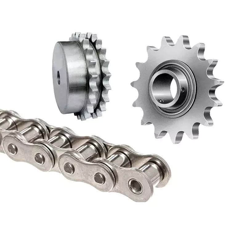
teeth
There are many factors that determine the length and shape of a sprocket. The number of teeth on the sprocket is a consideration. The higher the number of teeth, the longer the life of the sprocket. Also, the higher the number, the better the wear resistance of the sprocket. Most sprockets have 17 teeth, but they can have more or less. Choosing the correct number of teeth for a sprocket will greatly increase the life of the sprocket and chain. The teeth are usually made of the same material as the sprockets, but there are some removable options as well. Another option is to harden the teeth of the sprocket, which will greatly increase the life of the sprocket. This process is often called induction hardening
While sprockets are sometimes made of metal, some are made of plastic or reinforced plastic. The design of the sprocket is similar to the design of the gear, but it is completely different. While they both have a wheel-like shape, the only difference between them is how they interact with different types of chains. In most cases, the sprocket and chain work together, similar to a bicycle chain assembly.
To determine the correct sprocket size, you need to know the size of the drive shaft, which will determine the size of the teeth. For example, a chain with a 3.5 pitch diameter needs a chainring with large teeth, while a chainring with a smaller pitch needs a chainring with small teeth. Pitch diameter or teeth per inch and bore (the hole through which the center of the sprocket passes through the drive shaft) are the two most important factors in determining sprocket size.
Hole
Each spring has two diameters – the shaft diameter and the spring bore. These measurements are important for spring assemblies and cavities. They usually hold a certain tolerance, depending on the customer’s tolerance requirements. Spring manufacturers typically design clearances according to standard manufacturing practices and recommend keeping bore and shaft diameters within a certain tolerance type.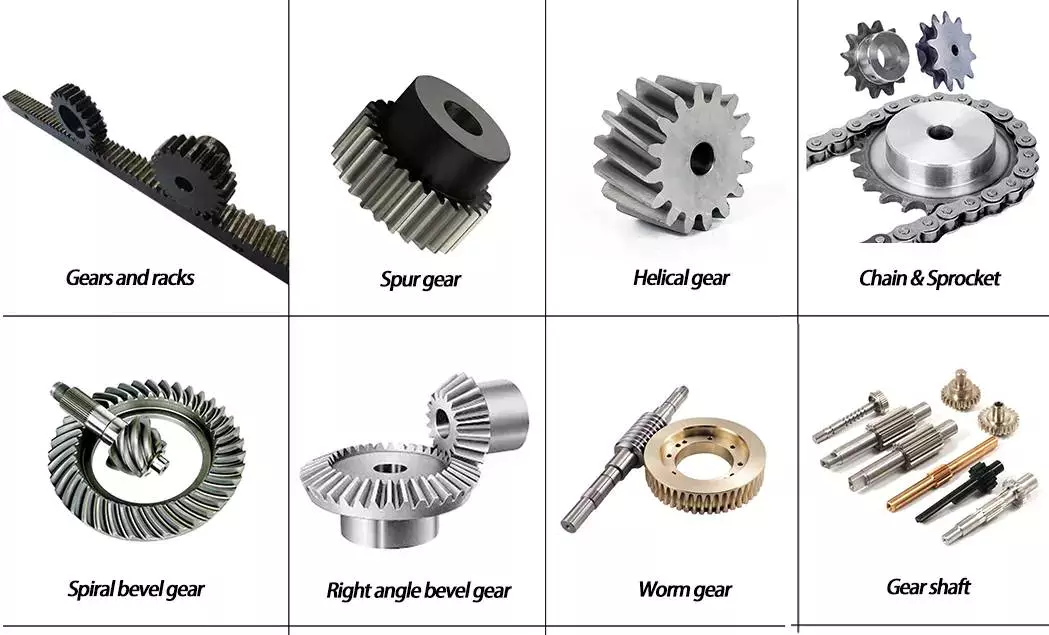
asphalt
Pitch is a property of a peak frequency that reflects its relative position in frequency space. The spacing of spikes can be measured using a method called neural coding. During this process, CF builds and indexes a series of single-fiber models. Each model predicts the rate response of the AN to any stimulus. These models have no free parameters and are used to find the excitation parameters that produce the most similar measurement curves.
In the past, baseball pitchers used spiked curves to throw harder knives. This type of curveball is similar to a fastball, but with a sharper hit. The resulting speed allows pitchers to throw harder knives. While it’s not a traditional curveball, it can help pitchers improve their QOP score by reducing the time it takes to complete a pitch.
In addition to estimating the pitch, these studies show that the phase relationship between the three harmonics has little effect on the pitch estimation for the pooled interval distribution. This finding is consistent with psychophysical observations of pitch-phase invariance. However, the phase relationship between unresolved and resolved harmonics may have a greater effect on pitch saliency.
editor by czh 2023-01-05